To test your mechanical keyboard wiring for faults, start with a visual inspection under magnification to spot broken traces, cold solder joints, or misoriented diodes. Use a multimeter in continuity mode to verify connections between switches, traces, and the controller. Check power and data lines for proper voltage and no shorts. Then, connect your keyboard to software like VIA to confirm each key registers correctly. Keep going to discover all the essential steps for a thorough diagnosis.
Understanding How Mechanical Keyboard Wiring Works
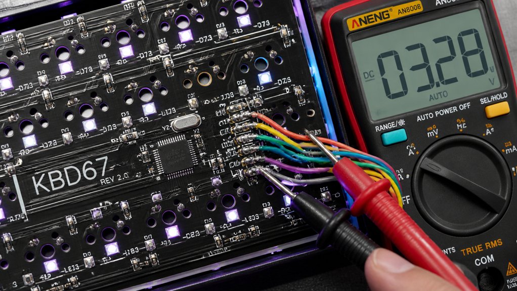
Understanding how mechanical keyboard wiring works begins with recognizing that each key connects a specific row and column on the PCB through a switch and diodes.
In a mechanical keyboard, the wiring uses a key matrix of rows and columns, traced on the PCB, to detect key presses. When you press a key, the switch completes an electrical circuit between its row and column lines, signaling the controller which key is pressed.
Diodes guarantee current flows only in one direction, preventing ghosting and enabling multiple keys to register simultaneously, known as n-key rollover.
Diodes ensure unidirectional current flow, preventing ghosting and supporting multiple key presses at once.
Maintaining low-resistance traces and solid solder joints is vital for reliable input detection. Faulty wiring, such as broken traces or misoriented diodes, can cause unregistered keys or erratic behavior, affecting your keyboard’s performance.
Additionally, understanding proper soldering techniques and the importance of high-quality solder wire alloy composition and flux can significantly reduce wiring faults and improve overall reliability.
Check Visual Indicators for Wiring Problems
To identify wiring problems in your mechanical keyboard, start with a thorough visual inspection of the circuitry and components.
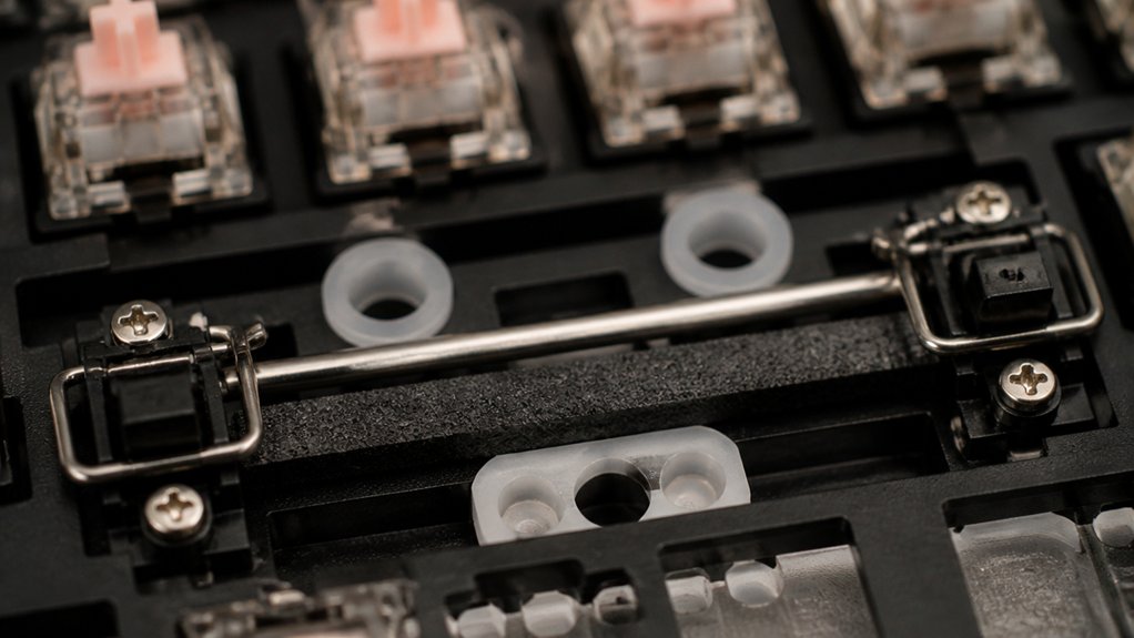
Use a magnifying glass or USB microscope to catch fine cracks near mounting points or flex areas, as hairline fractures can cause intermittent faults.
During your visual inspection, look for:
- Damaged traces, broken pads, or cold solder joints with a dull or grainy appearance
- Solder bridges that create shorts, disrupting the circuit
- Signs of corrosion, burn marks, or discoloration on wires or the PCB surface indicating overheating or shorts
Verify that all wires, connectors, and components like diodes are correctly oriented and firmly soldered per the schematic.
Confirm JST connections are straight, seated properly, and free of kinks or damage.
Additionally, inspecting the PCB’s material and heat resistance can help identify potential failure points caused by high soldering temperatures or mishandling.
Test Continuity Across Switches and Traces
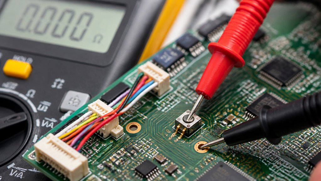
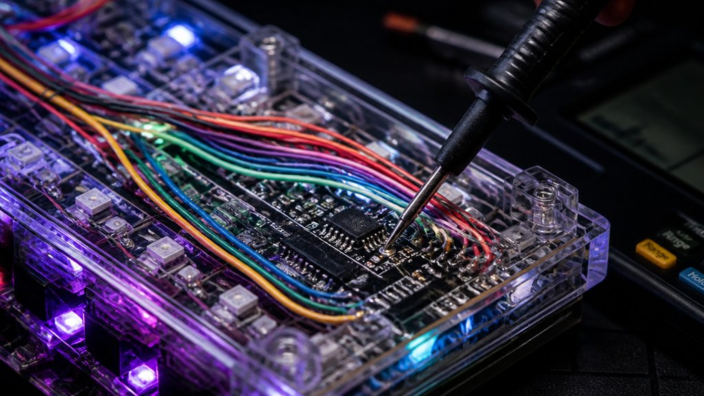
To guarantee your keyboard wiring is solid, start by testing continuity across switches and traces with a digital multimeter. Check that each key’s switch connects properly to its row and column traces and look for shorts or open circuits. Confirm that PCB pathways have low resistance to prevent faulty connections, and inspect solder joints for cold joints or bridges. Additionally, ensuring your multimeter has proper safety ratings can help prevent accidents during testing.
Checking Trace Continuity
Before testing for continuity, verify your digital multimeter is set to the correct mode to detect electrical connections.
To check a PCB, carefully probe both ends of each trace and switch solder joints. Look for audible beeps indicating good connections along the copper lines.
It’s important to:
- Test traces near mounting holes or flex points for cracks or damage
- Inspect solder joints with a magnifying glass for cold or weak solder connections
- Detect solder bridges that can cause shorts between traces or pins
Ensure the PCB is powered off and you’re using anti-static precautions.
Listening for continuity confirms the copper traces are intact and properly connected, helping you identify any broken or faulty paths before reassembly. Incorporating proper material compatibility considerations ensures the cleaning process doesn’t damage the PCB during testing.
Testing Switch Connections
When testing switch connections on a mechanical keyboard, you should use a digital multimeter set to continuity mode to determine if electrical connections are intact. Place the probes on the switch pins and check the printed circuit board (PCB) traces beneath. A beep or low resistance indicates a good connection.
Test each switch socket individually by shorting the two contact points with metal tweezers to verify if the keyboard correctly registers the keypress via test software or hardware.
Inspect the PCB’s trace resistance to identify any broken or damaged copper traces, which could cause open circuits. Confirm that diodes in the switch matrix are correctly oriented and show continuity in the proper direction.
Repeat these tests across all switches and matrix points to find cold solder joints, solder bridges, or broken connections that impair switch registration.
Additionally, using a high-quality soldering iron, like the professional-grade options, ensures precise and clean connections during repairs or reflow work.
Verify Power and Data Lines With a Multimeter
Start by checking the continuity of the power and data lines with your multimeter to verify there are no breaks along the traces. A flux residue can sometimes interfere with electrical connections, so ensure the area is clean before testing. Then, measure the voltage on the power rails to confirm a stable supply between 4.8V and 5.2V. Finally, inspect the USB connector pins for proper wiring and verify that ground continuity is solid across the PCB.
Check Power Continuity
Have you checked the continuity of your mechanical keyboard’s power and data lines with a multimeter? This step guarantees your keyboard PCB isn’t interrupted by broken traces or shorts.
Use a digital multimeter set to continuity mode to test several key points:
- Power rails on the keyboard PCB, confirming voltage falls within 4.8V to 5.2V.
- USB connector pins to the PCB’s power points, spotting damaged traces or faulty pins.
- Ground line continuity, maintaining a stable zero-volt reference for consistent performance.
When testing, listen for a beep or see a low resistance reading. This quick check pinpoints issues like cold solder joints or broken connections that could prevent proper power delivery.
Additionally, ensure the tested application method aligns with safety standards to prevent damage during diagnostics.
Test Data Line Resistance
To verify the integrity of your keyboard’s wiring, measuring the resistance of both power and data lines with a multimeter is essential.
For mechanical keyboards, use a digital multimeter set to resistance mode to check the trace resistance along the PCB’s data and power lines. Low resistance values, close to zero ohms, indicate a proper, continuous connection without damage or corrosion.
Confirm wiring integrity by checking continuity between USB connector pins (5V, GND, D+, D-) and their corresponding PCB points, ensuring no shorts or open circuits.
With the keyboard powered on, measure voltage levels on power rails, expecting 4.8V to 5.2V for USB power sources. Sudden drops or high resistance suggest damaged traces or faulty components impacting mechanical keyboard performance.
Understanding the importance of thermal management is crucial for maintaining the reliability of hot air rework stations during extensive PCB repairs.
Confirm Proper Grounding
Verifying proper grounding involves checking that all ground connections are solid and free of faults. Use a digital multimeter in continuity mode to verify zero ohms resistance between PCB ground points and the USB ground pin.
For power supplies, measure voltage levels on power rails—typically 5V and 3.3V—relative to ground, ensuring they fall within 4.8V to 5.2V for stable operation.
Inspect data lines (D+ and D−) for continuity from the USB connector through the PCB traces to the controller pins to catch any breaks or shorts. Additionally, confirm there are no unintended shorts to power or data lines by measuring resistance between ground and other lines, expecting high or infinite resistance.
Make sure the USB connector pins are properly soldered with no bent pins to maintain a reliable ground and data connection.
Checking for ESD protection on the PCB can help prevent damage caused by static discharge during testing and assembly.
Detect Shorts and Open Circuits Quickly
Wondering how to quickly identify wiring issues in your mechanical keyboard? Use a digital multimeter in continuity mode to check for shorts or open circuits. Probe between adjacent traces or solder pads on the PCB to detect unintended shorts—near-zero resistance indicates a short. Additionally, ensure the quality of your connections by inspecting the nozzle and tip features for proper contact points. For open circuits, verify continuity along each key switch row and column, listening for a beep or measuring low resistance to confirm connectivity. Inspect the USB connector pins and JST cable solder joints for breaks or intermittent connections. Visually examine traces with magnification, then electrically confirm open circuits by measuring resistance along suspect paths. Detect solder bridges by checking for near-zero resistance between isolated points, and remove excess solder to eliminate shorts. Quick testing helps guarantee your Keyboard wiring is sound before further troubleshooting or assembly.
Use Software Tools Like VIA to Test Your Keyboard
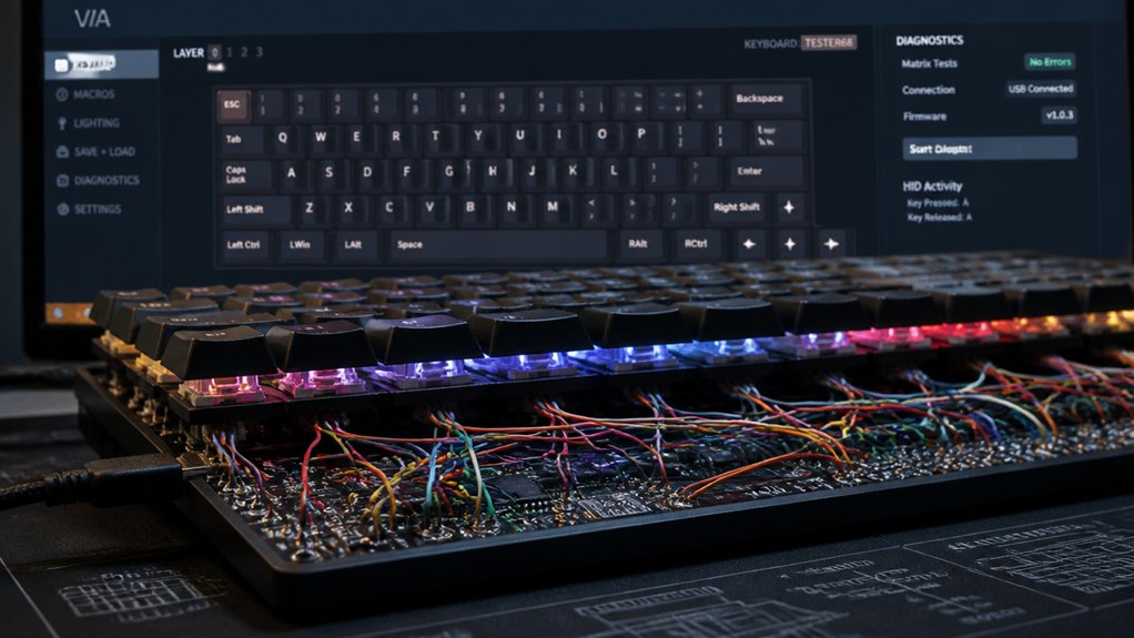
Have you considered using software tools like VIA to test your mechanical keyboard? VIA offers a visual interface that shows which keys register as pressed, making it easy to identify faulty or unresponsive switches.
To test with VIA, connect your keyboard PCB to your computer, launch the software, and observe the key matrix in real-time. This way, you can verify keypress signals without disassembly.
Using VIA helps detect intermittent faults and guarantees your wiring and switches are functioning correctly. It’s especially helpful for:
- Confirming key registration during prolonged presses
- Detecting hardware or firmware issues affecting key response
- Visually checking key connection status to reduce guesswork
VIA simplifies troubleshooting, boosting confidence that your wiring and switches are working properly.
Troubleshoot Wiring in Jumpers, Sockets, and Cables
When troubleshooting wiring issues with jumpers, sockets, and cables, the first step is to carefully inspect each component for physical damage or misalignment. Faulty components, such as bent pins or frayed cables, can cause intermittent connection problems.
Use tweezers to gently straighten bent pins on JST cable ends, ensuring proper contact. Verify all jumper wires and connector sockets are fully seated and correctly aligned on the PCB to prevent unreliable key matrix connections.
Test continuity with a digital multimeter to confirm there are no breaks or shorts in the wiring. Examine cables for kinks, sharp bends, or fraying that might degrade signals or cause open circuits.
If defects are found, replace damaged cables or reflow weak solder joints at JST connectors and sockets to eliminate faults.
Confirm Wiring Integrity Before Final Assembly
Before finalizing your keyboard assembly, it’s essential to verify the wiring integrity to prevent future issues. Make certain you use a multimeter in continuity mode to check for breaks or shorts.
Visually inspect all wiring for damaged traces, cold solder joints, bent pins on JST connectors, and alignment issues that could cause intermittent faults. To confirm proper connections, employ testing tools like VIA or dedicated keyboard fixtures to guarantee each key switch registers correctly and wiring matches every switch.
Additionally, make certain to check the USB connector pins and cables for proper data and power continuity. If you find any damaged cables or connectors, replace them now.
Conduct a thorough functional test by activating each switch with the wiring in place to detect any faults before final assembly.
Frequently Asked Questions
How to Check if a Keyboard Is Malfunctioning?
You can check if your keyboard malfunctions by testing each key with software like VIA or keyboardtester.com, inspecting for physical damage, and using a multimeter to verify electrical continuity across switches and traces.
How to Troubleshoot a Wired Keyboard?
To troubleshoot a wired keyboard, start with a visual inspection for damage, then use a multimeter to check continuity, voltage levels, and connections. Finally, test key registration with software and verify proper seating of all components.
How to Test if a Keyboard PCB Works?
You connect your PCB to a computer via USB, then use software like VIA or keyboardtester.com to verify key responses. Conduct visual inspections and electrical continuity tests with a multimeter to confirm all circuits function correctly.
How to Troubleshoot a Mechanical Keyboard?
To troubleshoot your mechanical keyboard, start by visually inspecting the PCB for damage, then use a multimeter to check connections, voltage levels, and shorts. Test keys with software to identify unresponsive switches or wiring issues.
In Summary
Now that you know how to test your mechanical keyboard wiring for faults, you can identify issues early and save time. By checking continuity, inspecting components, and using software tools, you guarantee reliable performance. Remember to verify all connections before final assembly to prevent future problems. With these steps, you’ll be more confident in troubleshooting and maintaining your keyboard, making sure it functions perfectly whenever you need it.