To identify electrical shorts in keyboards, start with a visual inspection looking for solder bridges, damaged pads, or debris. Use a multimeter to check for unintended connections between power and ground or switch pins. Inspect solder joints and switch placement for cold or misaligned contacts. Clean any solder bridges with flux and proper tools. Disconnect sections and test individually to isolate the fault. If you keep exploring, you’ll discover even more precise methods to troubleshoot effectively.
Understand Common Causes of Shorts in Mechanical Keyboards

Electrical shorts in mechanical keyboards often stem from common, preventable issues during assembly or repair. The first thing to check is for short circuits caused by bridged solder joints on switch pins or USB connector pins, often due to excess solder.
Misaligned or improperly seated switches, especially 5-pin types, can also lead to shorts if the stems don’t sit correctly through the PCB. USB connectors are another frequent source, with solder bridges between pins or cold solder joints that look dull.
Additionally, power rails and PCB traces may develop shorts from debris, damaged pads, or solder bridges, particularly around connectors and switch sockets. Proper soldering techniques and clean assembly are key—flux works best when used correctly to prevent unintended connections.
Inspect the PCB for Visible Damage and Bridges
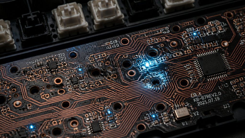
Start by carefully examining the PCB with a magnifying glass or microscope to spot any solder bridges or damaged traces.
Pay close attention to the power rails and USB connector areas, as these spots often develop shorts from bridged pins or pads.
Look for dull or cold solder joints, cracks, or signs of burning that could indicate problematic damage.
Check for Bridged Pads
Begin by carefully examining the keyboard’s PCB under a microscope to spot any solder bridges or physical damage between pads. Make sure to focus on power rails and densely packed areas, like USB connectors and switch contacts. Look for shiny or dull solder joints that seem to merge between pads or pins, as these often indicate bridging. Pay attention to discoloration, burns, or lifted pads that may signal previously caused shorts. Removing suspicious components or switches can help pull apart the circuit and isolate the short. Use this table to understand common issues:
| Problem | Visual Clue |
|---|---|
| Solder bridge between pads | Merged or shiny solder joints |
| Damaged or lifted pad | Discolored or torn pad |
| Excess solder | Buildup bridging components |
Proper inspection will help you pull out these faulty connections efficiently. Ensuring the stability and quality of the solder joints during initial assembly can prevent these issues from recurring.
Look for Cold Joints
Careful inspection of the PCB under a microscope can reveal cold solder joints that may cause intermittent shorts or connection issues. Look for dull, grainy, or cracked solder spots, especially around the USB connector and switch pins, as these areas endure mechanical stress and may have inadequate heat during soldering. Proper alloy composition promotes better joint integrity and reduces the likelihood of cold joints forming. Check for visible solder bridges or excess solder connecting adjacent pads or pins, which can directly cause shorts. When you spot suspect joints, reheat them with flux; a good joint will be shiny, smooth, and evenly flowed. If you find cold joints, remove and reseat the affected components, ensuring pins are properly seated and soldered. This process helps restore reliable connections and reduces the risk of electrical shorts caused by cold solder joints.
Identify Visible Damage
A thorough visual inspection of the PCB is essential to identify visible damage or potential shorts. Use good lighting or a microscope to closely examine solder joints, pads, and traces, especially where they meet. Look for bridged solder joints, particularly near the USB connector pins or switch contacts, which are common causes of shorts. Additionally, inspecting for flux residue, which can sometimes create conductive paths if not properly cleaned, is important. Check for physical damage such as burnt marks, lifted pads, or corrosion that might suggest a compromised trace. Flip the PCB and inspect the backside to guarantee switch stems are seated properly and not causing unintended contact. Also, scan for foreign conductive debris, solder splashes, or any foreign material on the surface that could bridge adjacent traces or pads. Addressing these visible issues helps prevent or confirm shorts effectively.
Check Solder Joints and Switches for Cold or Bridged Connections
To effectively identify cold or bridged connections, you should closely examine the solder joints and switch pins with a magnifying glass or microscope. Look for dull or grainy solder, which indicates cold solder joints that can cause poor contact or intermittent shorts. Check for solder bridges between adjacent switch pins or pads, as these create short circuits. If you find bridges, use flux and a chisel tip soldering iron to carefully perform drag soldering, cleaning up unwanted connections and ensuring shiny, proper wetting. Also, inspect the switch pins; if they’re misaligned or don’t protrude fully through the PCB, desolder and reseat them to prevent unreliable contacts or shorts. Pay special attention to the USB connector and nearby solder points, as these are common trouble spots. Incorporating proper soldering techniques and understanding solder joint quality can significantly reduce the risk of shorts and improve overall keyboard reliability.
Test Your Keyboard for Shorts Using a Multimeter
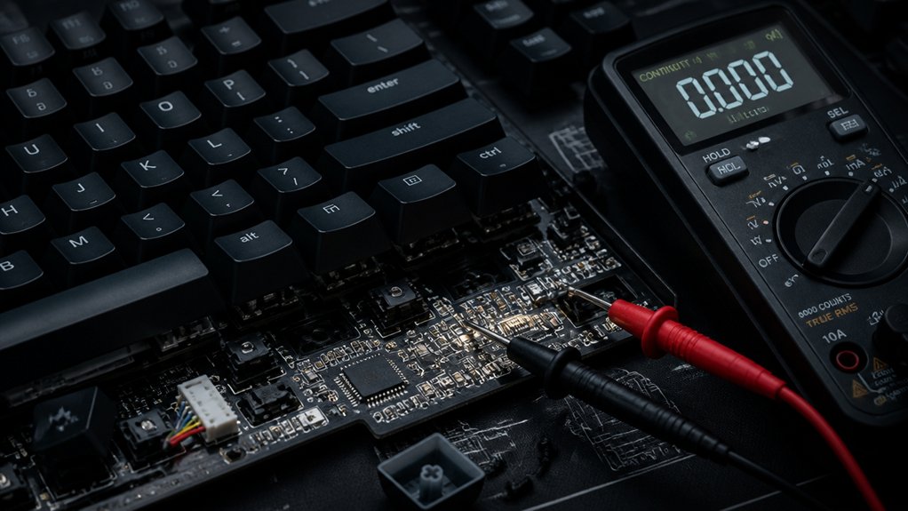
Using a multimeter to test for shorts in a keyboard allows you to identify problematic connections that could cause malfunction. First, set your multimeter to the continuity or resistance mode.
Disconnect the keyboard from power and USB to prevent damage or false readings. Probe between power rails, such as 5V and ground, or along traces suspected of shorting. Look for unusually low resistance indicating a short circuit.
Next, inspect switch pins and USB connector pads individually, measuring resistance to detect bridged or solder-bridged contacts. To pinpoint the source of a short, test each component or section separately. You may need to desolder or lift pins to isolate problem areas.
This systematic approach helps you accurately locate shorts, ensuring correct repairs or replacements. Incorporating the right multimeter features, like auto-ranging, can make troubleshooting faster and more precise.
Identify Problem Areas by Disconnecting Sections and Re-Testing
When troubleshooting a keyboard for shorts, isolating sections by disconnecting them can pinpoint problem areas effectively. Start by unplugging components like the USB connector, switch rows, or LED circuits, then test each isolated area with a multimeter on continuity or resistance mode. Look for low resistance readings that indicate a short. Proper selection of cleaning products, such as high-purity IPA, can help prevent residue buildup that might cause shorts. Focus initially on critical areas such as power rails or USB pads, disconnecting these to see if the short disappears. After testing each section, reconnect them one at a time, rechecking for shorts. This sequential approach helps you narrow down the exact location of the problem. Removing or unplugging switches, diodes, or other components within a section can further reveal the specific source of the short, streamlining your troubleshooting process.
Examine USB and Internal Connectors for Pinbridges or Damage
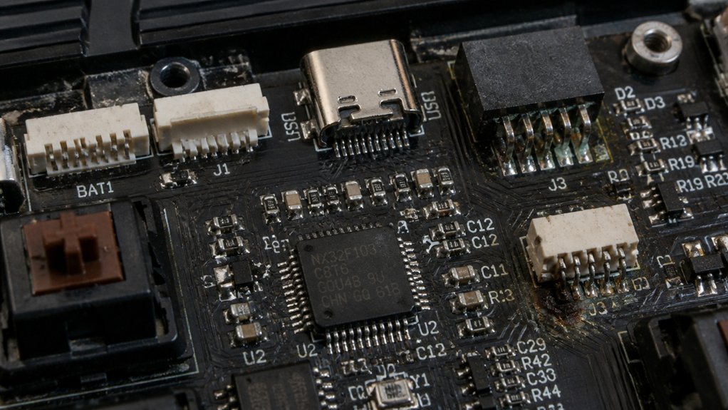
Inspecting USB and internal connectors closely can reveal hidden issues like bridged pins or physical damage that cause shorts. Use magnification to identify solder bridges, cold solder joints, or bent pins that might disrupt connections. A new approach is to verify proper MCU placement and soldering quality, as improper mounting can also lead to shorts or connection problems. USB connector shorts often trigger warnings such as “USB device drawing too much power,” signaling pin bridges or wiring faults. Check for dull, cold solder joints at connector pins, which can produce intermittent short circuits or connection failures. To troubleshoot, apply flux and use drag soldering techniques with a chisel tip soldering iron to carefully remove any solder bridges across pins. If you spot bent or corroded pins, reseat or replace the connector as needed. A thorough visual inspection is key to diagnosing and resolving internal shorts caused by connector issues.
Verify Proper Switch Seating and Alignment to Prevent Shorts
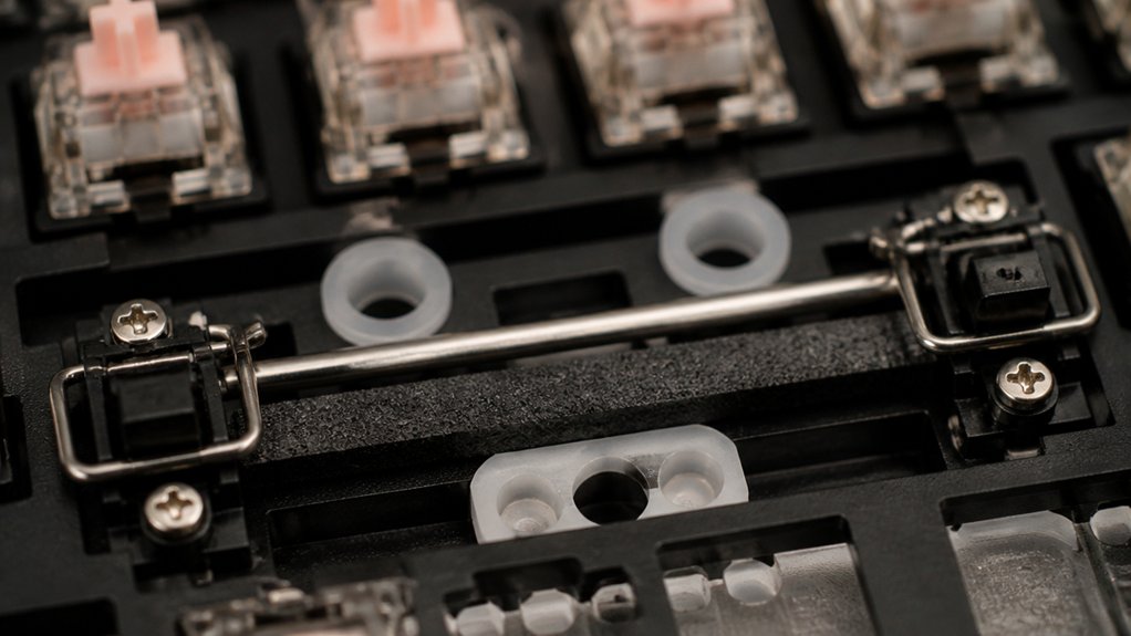
Guaranteeing switches are properly seated and aligned is essential for preventing shorts that can disrupt keyboard function. Check that switch stems protrude slightly from the back side of the PCB, confirming they’re fully seated and aligned.
For 5-pin switches, push firmly until all pins are fully inserted to avoid partial contacts that could cause shorts. Misaligned switches may create inconsistent or unstable connections, increasing the risk of shorts between adjacent pads.
If a switch isn’t flush with the PCB surface, carefully desolder and reseat it to prevent bridging or other shorts. Proper installation also reduces physical stress on pins and pads, which can deform components and lead to accidental shorts.
Taking the time to verify switch seating guarantees a stable, reliable connection and minimizes short circuits.
Clean and Fix Solder Bridges With Flux and Proper Tools
Using proper tools and techniques to clean and fix solder bridges is key to maintaining a reliable keyboard connection. Start with a high-quality, electronics-specific flux, like the Kester Rosin Liquid Flux Pen, to dissolve solder bridges and promote smooth solder flow on the PCB.
Use a chisel tip iron with fresh flux for drag soldering, allowing controlled removal of excess solder between USB pins and switch contacts. Incrementally add solder while heating the pins to reactivate flux and clean bridged areas without damaging components.
Proper flux application prevents new solder bridges and guarantees shiny, solid joints on switch pins and connectors. After fixing, thoroughly clean the area to remove flux residues, preventing conductivity issues or corrosion that could cause future shorts. Additionally, selecting a compatible flux remover can help ensure residual flux is completely eliminated, maintaining the long-term cleanliness and reliability of your PCB.
Use External Power Supplies or Test Fixtures for Safe Troubleshooting
When troubleshooting keyboard shorts, applying an external power supply or test fixture offers a safer alternative to powering the device directly. Using one with current limiting prevents damage from shorts and guarantees safe testing. Connect the keyboard to a test fixture designed to isolate circuits and detect shorts by monitoring individual sections. Employ a multimeter or continuity tester on the fixture to identify low-resistance paths. Opt for USB power supplies with built-in overcurrent protection to avoid excessive current draw. Segment power to different parts of the keyboard via the fixture to quickly localize the short. This approach minimizes risks and speeds up diagnosis.
| Power Source | Testing Method | Safety Feature |
|---|---|---|
| External with current limit | Use test fixture to isolate segments | Built-in overcurrent protection |
| USB power supplies | Continuity testing with multimeter | Short detection capability |
| Segmented power supply | Monitor individual circuit sections | Avoid damaging power flow |
Re-Test the Entire Circuit to Confirm the Short Is Resolved
Once you’ve repaired the suspected short, re-test the entire circuit to verify the issue is truly resolved. Use a multimeter to check for unintended connections and power rails, and power up the keyboard to observe its behavior. Confirm that all switches function normally and no new shorts or errors appear before finalizing the repair. Additionally, verifying the diode polarity ensures that the protection components are correctly oriented to prevent future issues.
Verify Short Clearance
After repairing a suspected short in your keyboard, the next essential step is to re-test the entire circuit thoroughly. Use a multimeter set to continuity or resistance mode to verify that no residual shorts remain. Check all previously bridged pins or pads, especially around USB connectors and switch contacts, ensuring they show normal resistance values and no unintended connections. Power on the keyboard and monitor for warning signs like USB overload messages, and confirm it draws the expected current without errors. Additionally, verify that all switches and components function correctly and consistently. For extra assurance, perform a final visual inspection with a microscope or magnifier to confirm solder joints and component placements are neat, free from bridging, debris, or damage. Incorporating precise temperature regulation during rework can help prevent future shorts caused by overheating or cold solder joints.
Conduct Functionality Test
To confirm the short has been effectively eliminated, you should now perform a thorough functionality test of the entire keyboard circuit. Power on the keyboard and test all keys to guarantee they respond correctly without unintentional signals or ghosting.
Use a multimeter in continuity mode across suspected circuit paths to verify no unintended connections remain. Check the USB connection for stability and look for any power warnings, which could indicate ongoing shorts.
Run diagnostic software or keyboard testing tools to detect stuck or misfiring keys. Additionally, type normally to observe if key actuation is consistent, without dropouts or errors.
Completing these steps verifies that the short is truly resolved and that the keyboard functions properly under normal use.
Frequently Asked Questions
How to Identify an Electrical Short?
You identify an electrical short by visually inspecting the PCB carefully, checking for bridged pads, and testing with a multimeter in continuity mode. Focus on USB and switch areas, resolder suspect joints, and reflow solder to find the short.
How to Know if a Keyboard Is Shorted?
If your keyboard’s causing power warnings or keys behave erratically, you likely have a short. Visually inspect the PCB for bridged solder joints, use a multimeter for continuity, and test suspect sections to confirm.
What Devices Can Be Used to Find Shorts in a Circuit?
You can use a multimeter to measure resistance and check for low resistance or continuity between points. Additionally, tools like specialized testers, oscilloscopes, and USB fixtures help you detect shorts by monitoring voltage, current, or signaling irregularities.
What Tool Is Used to Find Electrical Shorts in Your Home?
You use a multimeter set to resistance or continuity mode to find electrical shorts in your home. De-energize the circuit first, then test conductors for unexpected low resistance or continuity, helping you pinpoint and isolate the short circuit safely.
In Summary
By following these steps, you’ll be able to identify and fix electrical shorts in your keyboard effectively. Regular inspection, proper testing with a multimeter, and careful cleaning can prevent future issues. Remember to handle components safely and verify your repairs thoroughly. With patience and attention to detail, you’ll keep your mechanical keyboard functioning smoothly and avoid costly replacements or damage down the line. Stay meticulous, and your keyboard will thank you!