To repair mechanical keyboard socket issues expertly, start by inspecting the sockets with magnification and using a multimeter to check for loose or broken solder joints and traces. Carefully resolder or replace faulty sockets, ensuring proper heat and clean connections. Fix lifted pads and damaged traces with jumper wires or conductive ink, and test thoroughly before reassembly. If you keep exploring, you’ll gain deeper insights into precise techniques to restore your keyboard’s reliability.
Understanding Hot-Swap Sockets and Their Common Failures
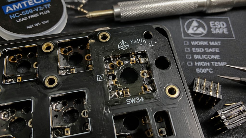
Have you ever wondered why some keys on your hot-swap mechanical keyboard become unreliable? It often comes down to issues with the hotswap sockets, which rest on the keyboard PCB.
These sockets use solder joints to connect electrically and physically to the PCB, but unlike direct soldered switches, they’re more fragile. Over time, loose or insufficient solder coverage on socket contacts can cause intermittent keypresses or complete switch failure, even if the switch pins seem secure.
Common signs include keys that require extra force or work unpredictably. Repairing involves re-soldering the sockets or ensuring they’re flush with the PCB. Proper switch insertion and careful mounting help prevent socket damage caused by uneven pressure or improper handling. Additionally, installation methods such as snap-in designs or soldered connections significantly impact socket longevity and reliability.
Safety Tips Before Repairing Your Keyboard
Before you begin repairing your keyboard’s hot-swap sockets, guaranteeing your safety and protecting the device are top priorities. Start by disconnecting your keyboard from power and grounding yourself with an anti-static wrist strap to prevent electrostatic discharge that could damage the socket or other components. Work on an anti-static mat to further protect sensitive parts. Use proper lighting and guarantee good ventilation, especially when working with solder, as fumes can be harmful. Wear safety glasses to shield your eyes from splashes and chemical-resistant gloves to avoid skin contact with flux and solder. Set your temperature-controlled soldering iron between 300–320°C, limiting heating time to 2–5 seconds per joint. Avoid repairs under warranty to prevent voiding coverage or causing irreversible damage. For best results, consider using a ceramic heating element for quick heat-up and precise control in your soldering process.
How to Inspect for Loose or Damaged Sockets
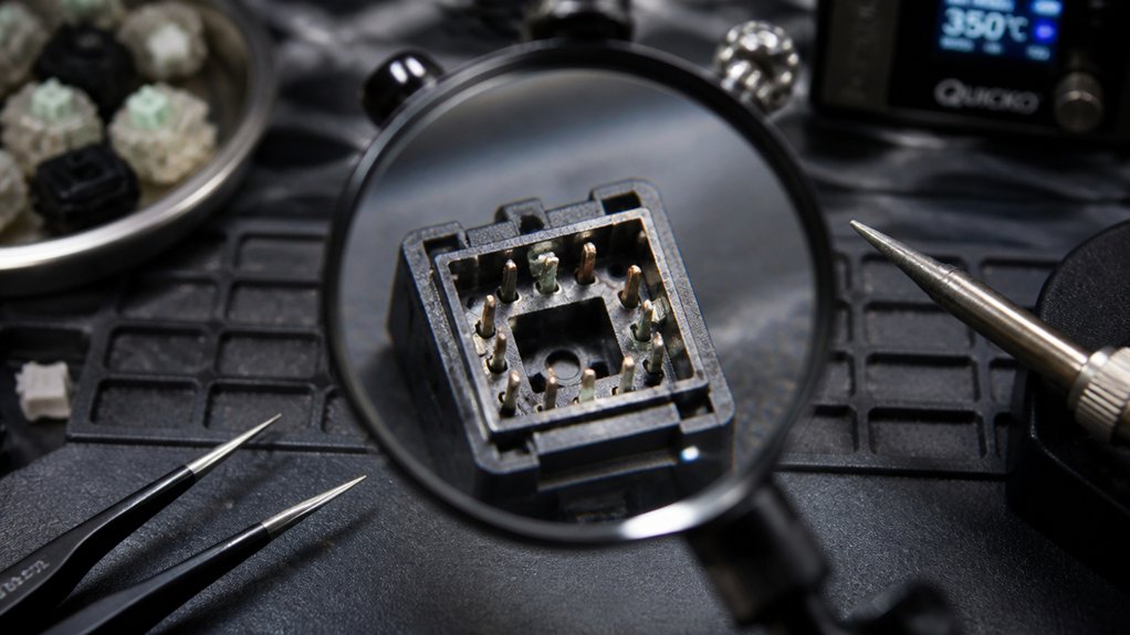
Inspecting your keyboard’s hot-swap sockets thoroughly is essential to identify any signs of looseness or damage that could cause connectivity issues.
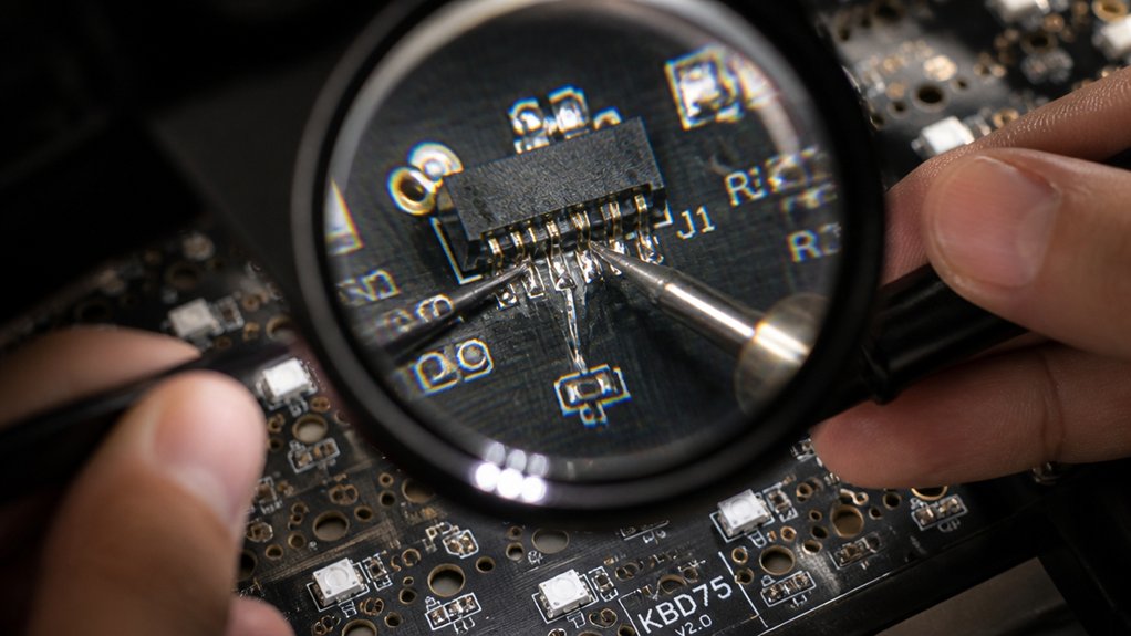
First, perform a visual inspection of the PCB around the socket for lifted pads or cracked traces, using at least 10x magnification. Next, gently wiggle the switch pin with tweezers to detect any loose hotswap socket or unstable fit. Then, examine solder joints on the socket’s contacts for dull, grainy spots indicating poor connection.
Finally, test each socket pin with a multimeter set to continuity mode to confirm the electrical connection to the PCB. Addressing these issues early helps prevent unreliable key registration or intermittent connection problems.
Diagnosing Socket Issues With Multimeter and Magnification
To effectively diagnose socket issues, you’ll want to use a digital multimeter in continuity mode to test each pin of the hotswap socket individually. Conduct continuity testing to verify each pin maintains a consistent electrical connection to the PCB traces, ruling out broken contacts or intermittent connections.
Use magnification tools or a USB microscope to inspect solder joints around the socket—look for dull, grainy areas that indicate cold solder joints or insufficient solder coverage on socket prongs. Check for lifted or damaged PCB pads, as hairline cracks or lifted copper can break continuity despite a physical appearance of intactness.
Gently wiggle the socket with tweezers to detect looseness or micro-movements that could cause intermittent contact, and verify that diode orientation and soldering are correct and intact. Additionally, understanding the safety ratings of your multimeter can help ensure safe and accurate testing, especially in high-voltage or sensitive circuit environments.
How to Resolder a Loose Hot-Swap Socket
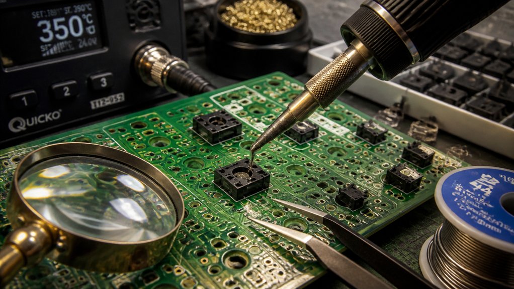
When a hot-swap socket becomes loose, resoldering it properly is essential for restoring reliable connections.
Start by inspecting the solder joints visually, ensuring there’s sufficient solder coverage and no grainy or cold joints. Next, apply flux to the socket contact prongs and preheat the solder joints. Create a clean pile of solder on the socket pins, ensuring a strong electrical and mechanical connection.
Use tweezers or a small tool to press the socket firmly against the PCB while reheating the solder to flow evenly. Limit soldering time to 2–5 seconds per joint to prevent damage and excess solder bridges. Incorporating a stable and heat-resistant PCB holder can help maintain the position of components during soldering, ensuring consistent results.
After finishing, test socket pin connectivity by inserting a switch and gently wiggling it to confirm secure contact and mounting.
Replacing Broken or Severed Sockets With Compatible Parts
Replacing broken or severed sockets requires selecting the correct type-specific component to guarantee compatibility with your keyboard. Identify whether your socket is MX-style or Choc, as using the wrong type can cause fit and function issues.
To remove a damaged socket, apply flux and heat both pads simultaneously, lifting the broken socket straight up to prevent PCB damage—especially to the solder mask. Pre-tin the PCB pads with solder before installing the replacement socket, guaranteeing a solid connection.
Reflow the solder carefully to avoid overflow and confirm the socket sits flush. If the socket is severely damaged, you can solder additional wires inside the prongs for added mechanical stress resistance and better electrical contact. Ensuring proper flux application and controlled heat management, as outlined in the flux content section, is essential for a successful repair.
Use QMK Toolbox for testing the connection before final assembly.
Repairing Lifted Pads and Damaged PCB Traces for Reliable Connections
When repairing lifted pads or damaged traces, start by securely reattaching the pad with super glue, then soldering it in place.
For broken traces under 10mm, use conductive silver ink or thin jumper wires to restore electrical continuity cleanly.
Always test your repairs with a multimeter to verify proper connections before reassembling your keyboard, and consider using a flux remover to ensure a clean surface for better adhesion and solderability.
Techniques for Pad Reattachment
Reattaching lifted pads and repairing damaged PCB traces require careful preparation to guarantee reliable connections. First, secure lifted pads with super glue to hold them in place before soldering, preventing further damage from heat. Use a soldering iron to carefully reattach the pad, applying rosin-core solder to improve bonding.
To reconnect detached pads or damaged areas, employ a thin insulated wire, pre-tinned with solder, and confirm proper routing. Before finalizing, test the connection with a multimeter in continuity mode to verify proper electrical contact and avoid shorts.
If traces are cracked under 10mm, consider using conductive silver paint or epoxy as an alternative patch. These steps help assure a solid, durable repair for your mechanical keyboard socket. Proper maintenance of tools and careful handling during repair can prevent further damage and ensure long-lasting connections.
Repairing and Reinforcing Traces
To repair and reinforce traces effectively, start by carefully scraping away the solder mask over the damaged area to expose the underlying copper. If you notice a loose socket or a lifted copper pad, secure it with super glue or a copper pad kit before soldering for reliable contact.
For damaged traces under 10mm, use a multimeter to check continuity, confirming the repair’s success. If traces are ripped or broken, bridge them with thin wires, connecting to nearby vias, component leads, or pads to restore the keyboard matrix’s electrical path.
When repairing, pre-tin both the pad and jumper wires to guarantee smooth solder flow, achieving a solid bond without excessive heat. Always verify the repair with a multimeter and confirm proper function before reassembling. Using precise temperature control can help prevent further damage during rework.
How to Re-Establish Circuit Continuity With Patch Wires
To re-establish circuit continuity, start by pinpointing the break points using a multimeter in continuity mode.
Then, select thin, compatible patch wires and solder them carefully between the damaged socket’s pads and the correct adjacent socket pins.
Verify the connections are solid and correctly oriented to maintain proper row/column wiring and prevent shorts.
Identifying Break Points
How can you effectively identify break points in a damaged mechanical keyboard socket? Start by inspecting the hotswap socket for lifted pads or visible damage.
Use a multimeter to test for broken circuits, focusing on the diode connection and trace continuity. Carefully check the soldering points, especially where the patch wire will connect, to identify weak or broken solder joints.
Verify the adjacent switch’s non-diode end within the matrix layout to guarantee correct wiring paths. Examine if the lifted pads are still connected to their respective circuits or if they need re-establishing with patch wires.
Focus on the bottom pin of the damaged socket where the diode is attached, as it’s a common break point. Precise testing guarantees you locate the exact points needing repair, and consulting ESD protection diodes can help ensure reliable transient suppression if replacing components.
Selecting Correct Patch Wires
When selecting patch wires to restore circuit continuity, it’s crucial to guarantee they connect the correct pads in the key matrix layout. Use a multimeter to test continuity between the ripped socket pad and the adjacent, functioning pad sharing the same row or column wire.
Identify the “left end” of the switch pad, avoiding shorts between traces. Choose thin, flexible patch wires that can be securely soldered to the socket arm or lifted pad and to the diode or neighboring pad’s top pins.
Before permanent soldering, test the setup by bridging the patch wires with tweezers while pressing the key, making certain proper key registration. Proper flux application ensures strong, clean solder joints that resist corrosion and improve conductivity.
Always maintain correct diode polarity and matrix orientation to prevent ghosting or damage. Proper selection of patch wires guarantees reliable restoration of circuit function.
Soldering for Connectivity
Securing reliable circuit continuity with patch wires involves precise soldering techniques. First, verify the PCB is stable, then tin the patch wire and the solder points on the socket or trace. Use a multimeter to check for continuity before soldering, confirming the correct connection point.
Follow these steps:
- Apply flux to the damaged pad or trace, then solder a fine gauge patch wire to reconnect the broken circuit, attaching only to top or bottom pins as appropriate.
- Quickly heat the iron (2–5 seconds) to avoid PCB damage, guaranteeing the solder flows smoothly and stays flush.
- Confirm continuity with a multimeter after soldering, verifying the reconnect is solid.
- Test the socket through key matrix scans and stress testing to confirm proper operation.
Testing Your Repair: Continuity, Voltage, and Functionality Checks
After completing your repair, it’s essential to verify that the connections and components are functioning correctly before reassembling your keyboard. Use a multimeter in continuity mode to check the solder joints and key matrix connections, guaranteeing there are no breaks or cold joints.
Test the voltage rails on the PCB by setting your multimeter to voltage mode, confirming a steady 4.8V to 5.2V from the USB power supply. Check diode functionality by testing forward and reverse bias conduction, which helps prevent ghosting issues.
Finally, perform a physical functionality test by bridging switch pads with tweezers and observing registration in VIA or QMK Firmware tools. Conduct stress tests by typing extensively to ensure consistent key registration and stability.
Common Mistakes to Avoid When Working on Hot-Swap Sockets
Working on hot-swap sockets requires careful attention to detail, as these components are delicate and easily damaged if handled improperly. Avoid inserting a switch at an angle or on an uneven surface, which can cause the socket to pop out or break.
Never apply excessive force when pressing switches into the socket; since they’re held by solder joints, too much pressure can damage them. Don’t attempt to repair or reflow hotswap sockets if the keyboard is still under warranty, as this might void it.
Also, neglecting to inspect solder joints on the socket contacts can lead to intermittent switch issues. Finally, skipping the diode connection step during repairs can cause ghosting or damage to the PCB, so always make certain it’s properly installed.
Frequently Asked Questions
What Is the Lifespan of Hot Swap Sockets?
Hot swap sockets typically last between a few hundred to over a thousand switch insertions, depending on usage. You can extend their lifespan by gentle handling, regular cleaning, and reflowing solder if contacts become loose or intermittent, avoiding premature replacement.
How to Repair a Hotswap Socket on a Mechanical Keyboard?
To repair a hotswap socket, you clean it, reflow solder, or replace it if damaged. If needed, reconnect broken pads with a wire, secure ripped ones with super glue, then guarantee proper soldering and test before reassembling.
Can Mechanical Keyboards Be Repaired?
Yes, your mechanical keyboard can be repaired. You can fix broken sockets, damaged PCBs, and solder joint issues with proper tools, patience, and knowledge, often restoring the keyboard to full functioning without needing complete replacement.
Is It Worth Repairing a Broken Keyboard?
Yes, repairing a broken keyboard is often worth it if it’s sentimental or high-value, and damage is manageable with soldering or patching. However, extensive damage or costly repairs may make replacement more practical.
In Summary
When repairing hot-swap sockets, take your time and follow safety precautions. Carefully inspect and diagnose the issue, then gently resolder or patch damaged areas. Double-check your work with continuity tests and confirm everything functions properly before reassembling. Avoid rushing, and don’t forget to prioritize safety. With patience and attention to detail, you can restore your mechanical keyboard’s reliability and enjoy a seamless typing experience once again.