
To build custom split keyboard PCBs for programmers, start by designing your layout with ergonomic software like Ergogen, ensuring it matches your workflow and comfort needs. Select and place components such as microcontrollers, wireless modules, and hot-swap sockets carefully for modular, wireless operation. Prepare your Gerber files for manufacturing, then create the case in Fusion 360. After soldering and installing components, set up firmware like ZMK to customize layers, wireless functions, and user shortcuts. Keep exploring for detailed guidance on each step.
Why Build a Custom Split Keyboard for Programming?

Building a custom split keyboard for programming makes sense because it allows you to personalize your ergonomic setup to reduce wrist strain and improve efficiency.
A custom keyboard lets you craft a layout tailored to your needs, with split designs that promote natural wrist positioning. Programmers benefit from ortholinear or column staggered layouts, which minimize finger travel and boost typing speed.
Custom layouts with split designs improve wrist comfort and increase typing efficiency for programmers.
You can include secondary layers for programming symbols like parentheses and brackets on the home row, reducing hand movement. Wireless split keyboards create a clutter-free workspace, enhancing focus and comfort.
You can also modify layouts to match your muscle memory, especially if you’re used to MacBook keyboards. Choosing the right PCB layout—such as split or ortholinear—impacts your typing posture and ergonomics.
Custom keyboards give you the flexibility to enhance comfort, efficiency, and productivity during long coding sessions.
Designing an Ergonomic Layout With Ergogen Software
To create an ergonomic layout tailored to your needs, Ergogen software provides powerful tools that use editable text files with variables like cx and cy to precisely define key positions and dimensions. You can design a custom keyboard layout by specifying key locations within rectangular grids, allowing for comfortable spacing and filleted edges. The software supports split keyboard configurations, enabling you to define separate halves with balanced key distributions and include split-specific components like microcontrollers. Additionally, you can add secondary layers to access functions like parentheses or brackets, maintaining muscle memory with standard MacBook layouts. Ergogen generates PCB designs with hot-swappable footprints for low-profile Choc switches and accurate microcontroller placement, streamlining the creation of ergonomic, wireless split keyboard PCBs. These features facilitate personalization to match ergonomic design principles from the latest keyboard trends, ensuring a comfortable and efficient typing experience.
Selecting and Placing PCB Components for Wireless Split Models

When selecting components for your wireless split keyboard, focus on positioning microcontrollers and batteries to maximize space efficiency and maintain a clean design.
Place the microcontroller roughly 9 mm below and 2 mm left of the inner column of the number row to optimize electrical pathways and align with the key matrix.
Additionally, design your layout to support reliable wireless communication between halves while minimizing visible wiring and clutter. For optimal performance, consider integrating power management features to ensure safe and efficient charging of your wireless modules.
Component Placement Strategies
Designing the component placement for a wireless split keyboard PCB requires careful planning to guarantee both functionality and maintain a clean appearance. You should duplicate critical components like controllers, batteries, and wireless modules on each half to enable independent operation and seamless sync, ensuring wireless functionality. Utilizing a hot-swappable PCB can simplify switch replacement and maintenance. Place controllers such as the nice!nano with Bluetooth underneath the PCB to keep the surface uncluttered. Position batteries beneath the controllers to shape a wedge profile, improving ergonomics and supporting wireless operation. Strategically locate diodes near key switch inputs to prevent ghosting, enhancing input reliability. Additionally, place reset switches, battery on/off switches, and JST connectors near the edges for easy access, modularity, and efficient assembly, all while maintaining a neat, functional layout.
Wireless Connectivity Components
Selecting and placing wireless connectivity components for a split keyboard PCB involves careful consideration of both functionality and space. You’ll need duplicate wireless controllers, such as nice!nano modules with Bluetooth, on each half to enable independent yet synchronized communication.
Position these controllers underneath the PCB, along with batteries, to keep the design clean and ergonomic. Proper antenna placement on both halves guarantees reliable wireless links, with the right half communicating wirelessly to the left, which then connects to your computer.
Make sure your PCB design includes footprints for hot-swappable sockets, diodes, reset switches, and battery connectors. Power management components like on/off switches and JST battery plugs (compatible with 3.7 V lithium-ion batteries) are essential for maintaining wireless functionality and easy battery replacement. Incorporating tri-mode connectivity options can further enhance compatibility across different devices and platforms.
Preparing Gerber Files for PCB Manufacturing
Before submitting your Gerber files for manufacturing, verify they are properly prepared to meet all the requirements of your selected PCB fabricator. You should actually use tools like KiCad to generate accurate layouts and schematic files after running “ergogen .” Export the left and right halves as separate Gerber files, including drill files, guaranteeing 2 mm fillets and clearances. Compress each set into ZIP archives for submission. Confirm all footprints—hot-swappable switches, microcontrollers—are aligned and defined to avoid errors. Also, double-check the edge cut layers to reflect the final shape, with rounded corners and key cutouts sized at 14 mm x 14 mm for compatibility. Proper preparation guarantees smooth manufacturing and a flawless build process. Additionally, ensure your design incorporates proper component footprints to prevent fitting issues during assembly.
Creating Your Keyboard Case in Fusion 360

To create your keyboard case in Fusion 360, start by importing the Ergogen 3D outline exports, which provide accurate shapes and key cutouts sized at 14 mm x 14 mm for Choc switches. These exports serve as the foundation for designing your keyboard’s half shapes.
Subtract the key cutouts from the main outline and extrude the sections to 1.2 mm thickness, forming the base layer that holds switches securely. To enhance typing comfort, incorporate ergonomic features like wedge shapes and elevated tenting angles, mimicking the thin wedge design of a MacBook Air.
Add screw holes, supporting walls, and a baseplate to guarantee durability and stable assembly. Once complete, export your Fusion 360 design as STL files for 3D printing, allowing for iterative refinements before final production.
Leverage precise fit and alignment techniques inspired by high-quality aluminum keyboard cases to ensure a seamless build process and lasting durability.
Soldering Components and Installing Hot-Swap Sockets
Precision is essential when soldering components onto your existing keyboard PCB to guarantee reliable performance and durability. Use lead-free solder around 0.6 mm thick, and always work in a well-ventilated area or with fume extraction.
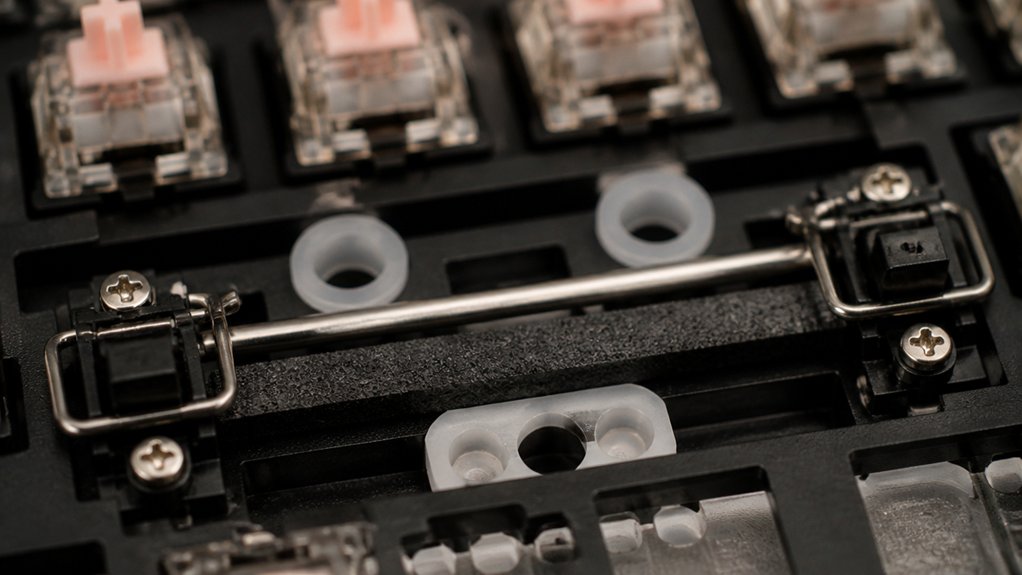
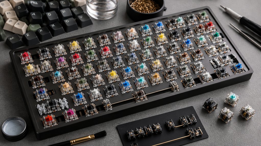
Carefully install hot-swap sockets for your key switches and controllers, making future switch replacements quick and solder-free. Position diodes correctly to avoid ghosting, soldering them precisely to maintain circuit integrity.
Utilize accessories like a solder stand, flux, tweezers, and a solder sucker to improve accuracy on tiny PCB pads and component leads. Securely connect additional parts such as reset switches and battery on/off switches, creating a modular and user-friendly design.
Proper soldering and socket installation guarantee your custom split keyboard functions smoothly and is easy to maintain.
Setting Up ZMK Firmware for Wireless and Layer Customization
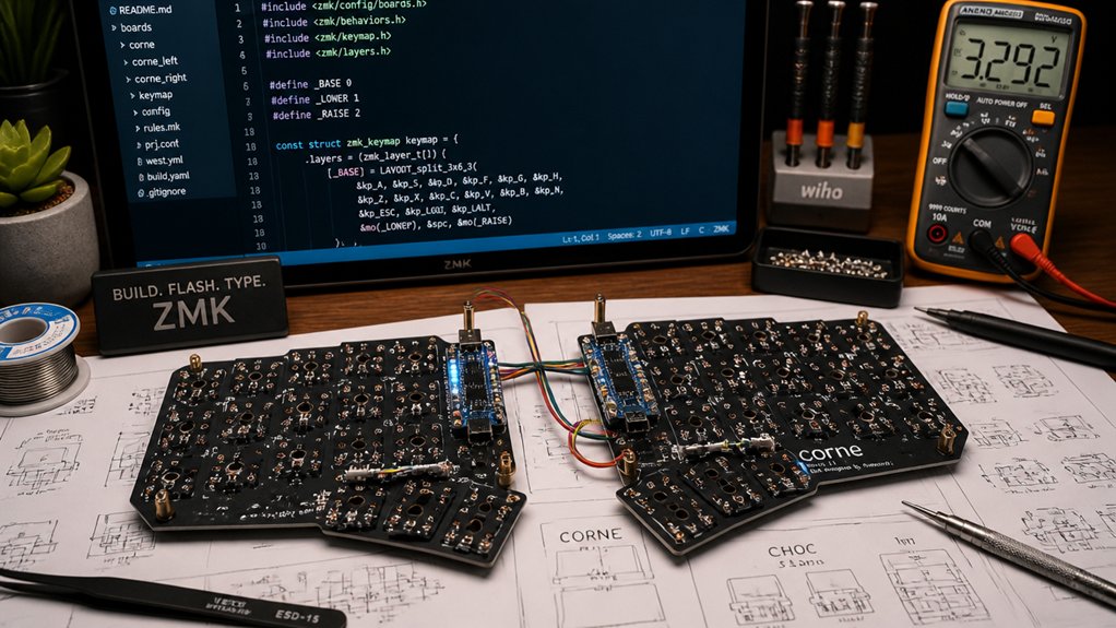
Setting up ZMK firmware for your custom split keyboard enables seamless wireless communication and flexible layer management. This allows you to customize arrow keys and other functions effortlessly across layers, making coding more intuitive.
To start, create a GitHub repo prefixed with “zmk-config-” and clone the official templates to simplify setup. Adjust the key configuration files (.dtsi, .overlay, keymap) to define your keyboard matrix, controller pins, and layers—adding custom layouts or function keys.
The nice!nano microcontroller pins are mapped to Pro Micro labels for compatibility. Additionally, utilizing hot-swappable switches can greatly enhance your customization process, allowing for easy switch replacements without soldering. When flashing firmware, double-tap each half’s reset button to mount as USB drives, copy the firmware files, and reset both halves simultaneously.
Now your wireless split keyboard is ready to enhance your programming experience, including smooth arrow key navigation.
Frequently Asked Questions
How Can I Optimize Keyboard Layout for Different Programming Languages?
You can optimize your keyboard layout for diverse programming languages by customizing key positions for common syntax, creating macros for frequently used code snippets, and adjusting layer functions to enhance efficiency and reduce finger movement during coding tasks.
What Are the Best Practices for Battery Life in Wireless Split Keyboards?
You should enable power-saving modes, such as deep sleep when idle, reduce backlight brightness, and use energy-efficient components. Regularly disconnect devices, keep firmware updated, and limit Bluetooth scans to extend battery life effectively.
How Do I Troubleshoot Connectivity Issues With ZMK Firmware?
You should check your Bluetooth connection, update your ZMK firmware, reset your device, and verify your configuration settings. Confirm batteries are charged, and try reconnecting or pairing again, paying attention to signal interference or range issues.
Can I Customize Keycaps for Ergonomic Comfort and Aesthetics?
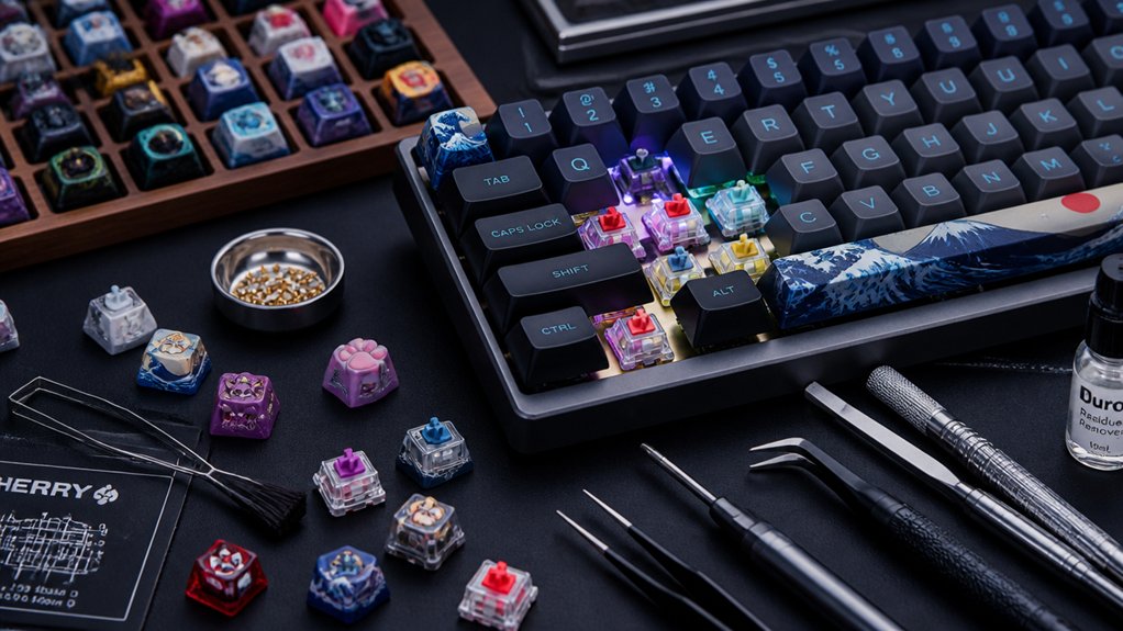
Yes, you can customize keycaps for ergonomic comfort and aesthetics by choosing different profiles, materials, and colors, or even designing your own. This personalization enhances your typing experience and makes your keyboard uniquely suited to your preferences.
What Safety Precautions Should I Follow During Soldering?
You should wear safety goggles to protect your eyes from solder splashes, work in a well-ventilated area to avoid inhaling fumes, and handle hot soldering iron carefully to prevent burns. Keep your workspace organized for safety.