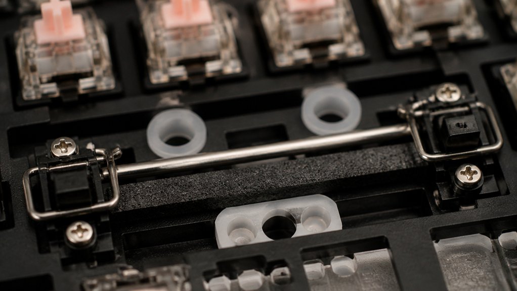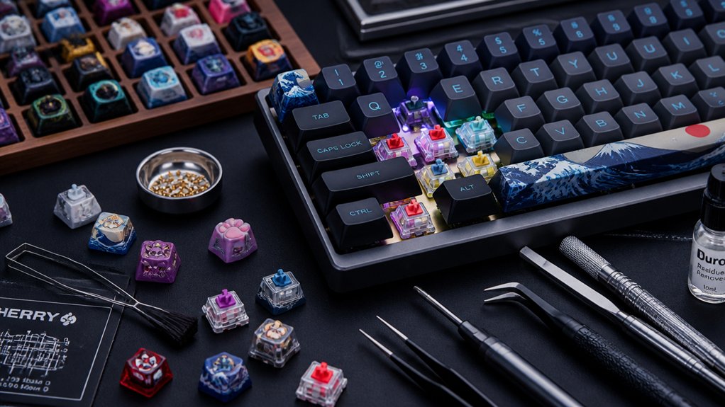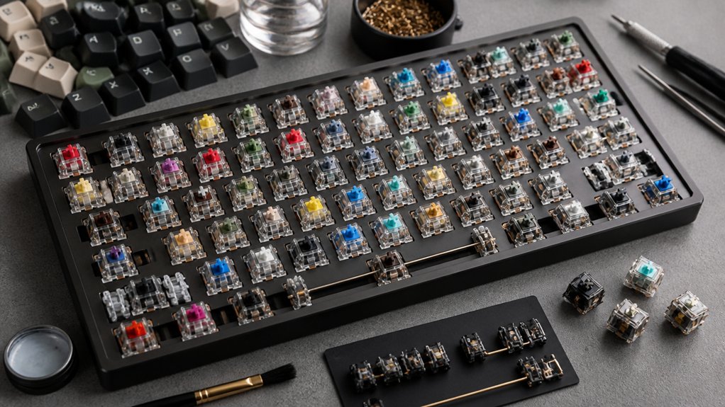
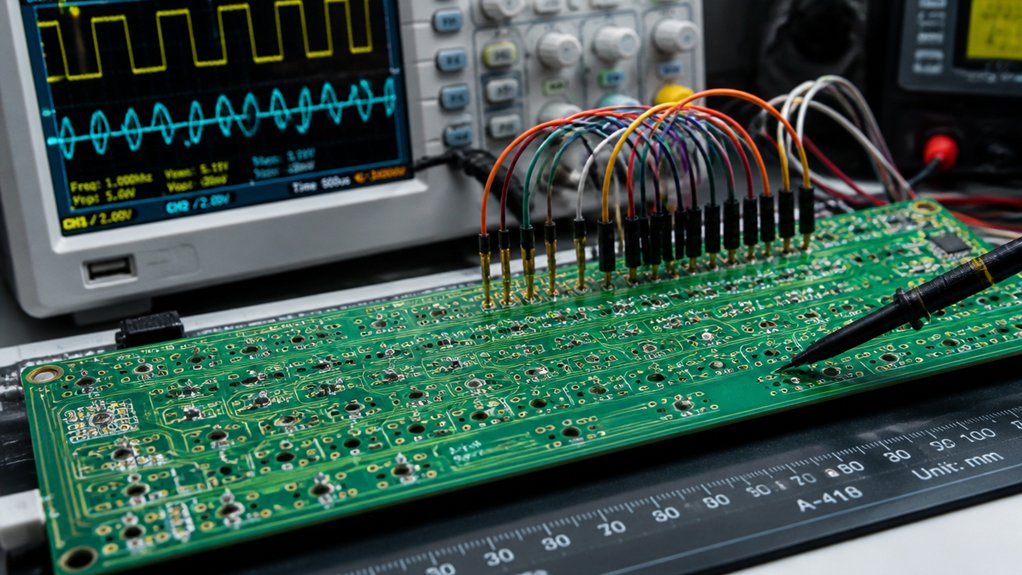
To test your mechanical keyboard’s circuitry, start with a thorough visual inspection using magnification tools to spot cold solder joints, broken traces, or corrosion. Use a multimeter to check for continuity and proper voltage levels on power rails and signal lines. Inspect and repair damaged traces or pads with conductive paint or jumper wires. Test switches, diodes, and connectors with a multimeter, confirming correct orientation and functioning. For more detailed methods, explore advanced techniques that help guarantee your keyboard works flawlessly.
How to Perform Basic Visual Inspection of Your Keyboard PCB
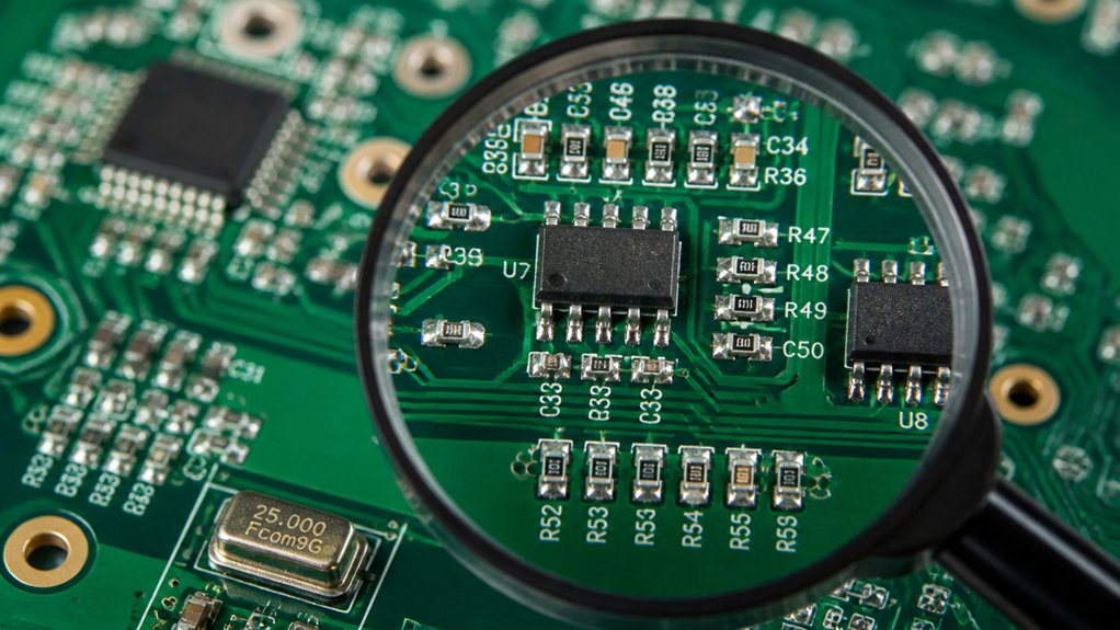
Performing a basic visual inspection of your keyboard PCB is an essential first step in troubleshooting and repairing your keyboard. When inspecting your mechanical keyboards, start by disconnecting the power and practicing anti-static precautions to prevent ESD damage.
Use magnifying tools like USB microscopes or magnifying glasses to spot common issues such as cold solder joints, solder bridges, burn marks, corrosion, and broken traces. Pay close attention to diode orientation, ensuring cathode black bands align with PCB markings, since incorrect polarity can disrupt the key matrix.
Also, examine the USB connector pins and JST cable solder joints for bent pins, proper alignment, and solid soldering to avoid power or data problems. Look carefully for hairline cracks or broken copper traces near mounting holes and flex points, repairing minor damage with conductive paint or jumper wires if needed. Utilizing multimeters to test continuity and voltage can further assist in diagnosing electrical issues on the PCB.
How to Use a Multimeter for Continuity and Voltage Testing
To effectively use a multimeter for continuity and voltage testing on your mechanical keyboard PCB, you’ll need to familiarize yourself with the device’s functions and settings. Set your digital multimeter to continuity mode (beep or low resistance) to verify connections between key matrix points, switch pins, diodes, and USB connector pins.
Measure voltage on power rails like the 5V USB and 3.3V microcontroller lines to guarantee they’re within the typical range of 4.8V to 5.2V. Check for shorts by testing continuity between power and ground rails; a beep indicates a potential short circuit.
Always disconnect power and use anti-static precautions before probing your printed circuit board to avoid false readings and damage. Proper testing helps confirm the PCB’s integrity before further repairs.
Additionally, ensuring that the temperature regulation of your hot air rework station is precise minimizes the risk of damaging sensitive components during testing and repairs.
How to Identify and Repair Damaged Traces and Broken Pads
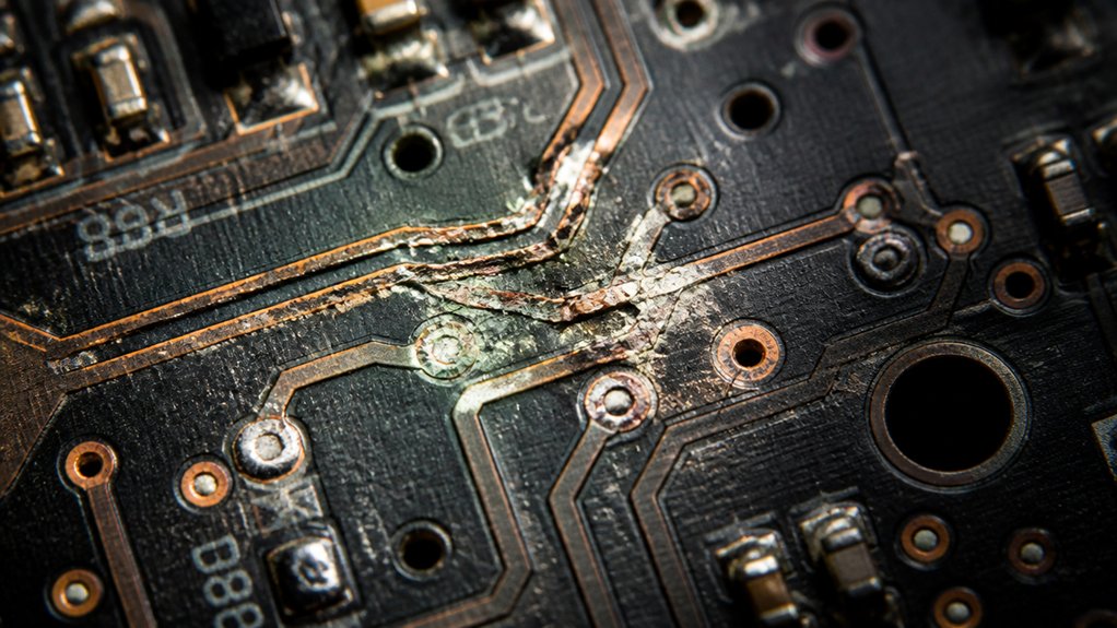
When inspecting your keyboard’s PCB after testing voltages and continuity, identifying damaged traces and broken pads becomes the next step toward repairs. Look for hairline cracks or broken copper paths, especially near mounting holes and flex points. Use magnifying tools to detect physical damage, which is common in mechanical PCBs. Consider using flux removal techniques to ensure no residual flux interferes with the repair process. Minor trace damage can often be repaired with conductive paint, restoring the electrical connection. For more severe breaks, carefully solder jumper wires to scraped copper areas. Broken or lifted pads may need thin insulated wires attached to vias or component leads for reliable reconnection. Always check the solder joints around damaged areas for cold joints or weak solder. If damage is extensive, consider replacing the PCB, especially if physical damage or corrosion compromises the keyboard’s reliability.
How to Test Switches, Diodes, and Connectors Effectively
Testing switches, diodes, and connectors thoroughly guarantees your keyboard’s reliability and proper functionality. If you need a PCB to test a mechanical keyboard, start by inspecting connectors and pins for damage. Use a digital multimeter in continuity mode to verify switch socket connections and diode orientation—ensure the diode’s black band aligns with PCB markings for correct key matrix operation.
To test mechanical switches, bridge the pins with metal tweezers and confirm key detection using software like VIA or keyboardtester.com. Visually examine JST and USB connectors for bent, misaligned, or damaged pins since they disrupt power and data signals. Additionally, consider inspecting ESD protection diodes within the circuit for proper operation, ensuring transient protection does not compromise signal integrity. Finally, measure voltage levels at USB (5V) and microcontroller (3.3V) rails, confirming they’re within range (4.8V–5.2V), and check decoupling capacitors for voltage drops.
Advanced Troubleshooting Techniques for Complex PCB Issues
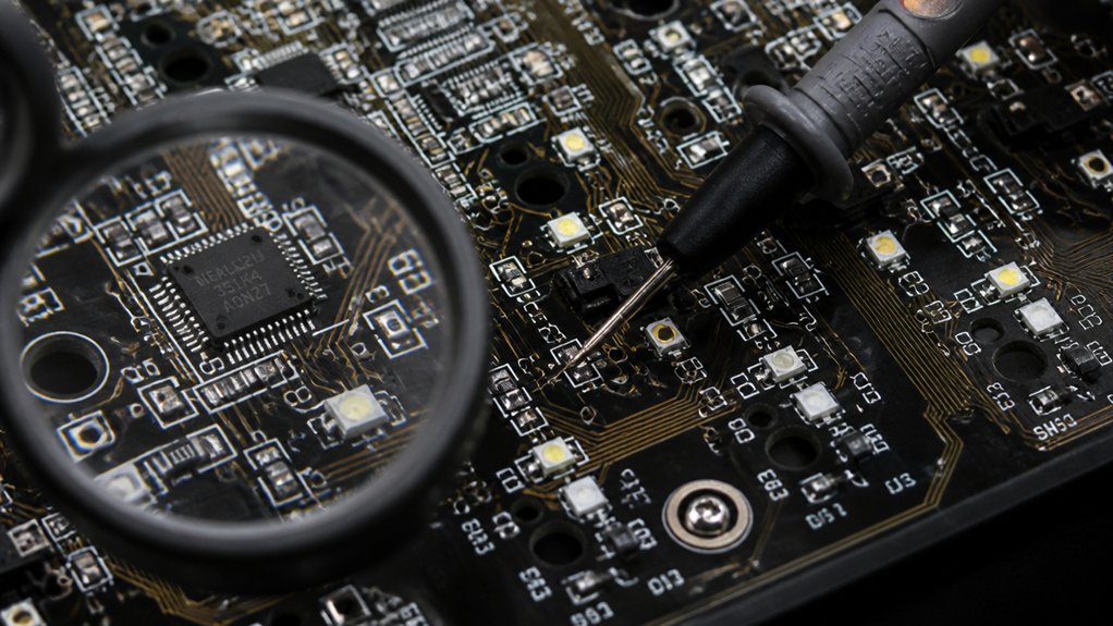
Advanced troubleshooting of complex PCB issues requires deploying specialized tools like oscilloscopes, LCR meters, and IV tracers to analyze signal quality and component behaviors that simple continuity checks can’t reveal. These tools help you verify all signals are stable and components function correctly. In-circuit testing (ICT) and JTAG debugging are key for pinpointing faults and directly programming microcontrollers. X-ray inspection and AOI are invaluable for detecting hidden cracks, cold solder joints, and solder bridges invisible to the naked eye. To visualize, here’s a quick picture:
| Tool | Purpose |
|---|---|
| Oscilloscope | Analyze signal integrity and waveforms |
| X-ray/AOI | Detect hidden solder issues |
| Thermal imaging | Identify overheating or shorts |
Use these techniques to cover a wide range of issues and verify the key feel of your keyboard remains consistent, especially considering the importance of hot-swap sockets in ensuring reliable switch retention and electrical contact.
Frequently Asked Questions
What Is the Best Software to Test Keyboards?
You should use VIA software, as it offers real-time key detection, supports layer keys and firmware functions, and immediately recognizes your PCB upon connection, providing extensive testing beyond basic key presses for accurate keyboard performance assessment.
What Are the 7 Types of PCB Testing Methods?
You should know the seven main PCB testing methods: visual inspection, flying probe testing, in-circuit testing, functional testing, automated optical inspection, X-ray inspection, and boundary scan testing. Each method checks different aspects of PCB quality and functionality.
What Is a 96% Keyboard Missing?
A 96% keyboard misses a dedicated number pad, extra function keys, and certain navigation or macro keys found on full-size models. It focuses on compactness, combining essential keys in a streamlined layout to save desk space.
How to Test a Keyboard PCB?
You connect the PCB to your computer and use testing software like VIA or keyboardtester.com to verify key recognition. Then, short switch pins with tweezers, visually inspect, and check continuity with a multimeter for proper electrical connections.
In Summary
Now that you know these efficient circuit testing methods, you’re better equipped to troubleshoot your mechanical keyboard. From simple visual inspections to advanced troubleshooting, each step helps guarantee your keyboard functions perfectly. Don’t forget to take your time and stay patient—issue resolution can sometimes take a bit of effort. With these techniques, you can identify and fix common problems, restoring your keyboard’s performance and extending its lifespan. Happy testing!