To test your mechanical keyboard PCB connections, start with a visual inspection using a magnifier to check for damage, lifted pads, or cold solder joints. Use a multimeter in continuity mode to verify switches, diodes, and traces are properly connected, checking for shorts and proper voltage levels. Test the switches while shorting pins and confirm the firmware recognizes key presses. If you want a full step-by-step approach, there’s more to explore below.
Core Principles of PCB Testing in Mechanical Keyboards
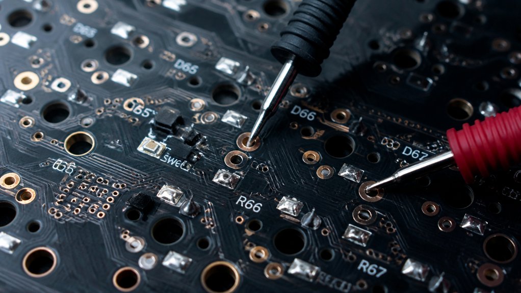
Understanding the core principles of PCB testing in mechanical keyboards is essential for guaranteeing your build functions correctly before soldering switches.
First, testing verifies electrical connectivity and identifies defects early. Using a multimeter to check traces for continuity helps detect damaged or broken connections. Shorting switch pin pads with metal tweezers confirms if the PCB registers key presses via testing software or the connected computer.
Reliable testing setups involve connecting the PCB through USB, guaranteeing stable power supply (around 5V), and following anti-static precautions. Specialized software like VIA’s Key Tester or keyboardtester.com can confirm keycode transmission, although firmware might handle special keys separately. For safety and accuracy, utilizing a multimeter with true RMS measurements can improve the reliability of voltage and resistance readings during testing.
How to Perform a Visual Inspection for PCB Damage
Start by disconnecting power and taking anti-static precautions to protect the PCB from static damage.
Use a magnifying tool to carefully check for physical damage, loose solder joints, and component misalignments.
Pay special attention to vulnerable areas like mounting holes and flex points where damage often occurs.
Ensuring the PCB remains stable during inspection is crucial; utilizing heavy bases and anti-slip features helps prevent movement that could obscure defects or cause further damage.
Check for Physical Damage
Before powering on your keyboard, perform a thorough visual inspection of the PCB to spot any physical damage. Carefully examine the keyboard PCB for burn marks, cracked or lifted pads, corrosion, or damaged traces.
Use a magnifying glass or USB microscope to inspect solder joints, component alignment, and near mounting holes for hairline cracks. Check diode orientation, ensuring the black band aligns with PCB markings to prevent key matrix issues.
Carefully examine USB connector pins and JST cable ends for bent or misaligned contacts that could cause connection problems. Look for solder bridges that might create shorts, missing components, or signs of physical stress, such as bent or broken parts.
These visual cues help identify potential issues before testing the key function or powering the keyboard. To prevent future connectivity problems, inspect flux residues that may be present around solder joints, as residual flux can cause corrosion over time flux residue.
Inspect Solder Joints
Careful visual inspection of solder joints can reveal problems that might cause your keyboard to malfunction. Use a magnifying glass or USB microscope to spot issues like dull, grainy, or cracked surfaces, which indicate cold or weak solder connections. Look closely for solder bridges that could short-circuit adjacent pads or traces. Check the component polarity to confirm diodes and other parts match PCB markings. Also, examine for physical damage such as burn marks, corrosion, lifted pads, or broken traces, especially near mounting holes or flex points. Use your soldering iron to reflow suspect joints for better connections. Keep power disconnected and take anti-static precautions during inspection. When selecting solder wire, consider the alloy composition, flux type, and melting point to ensure durable, reliable joints.
Identify Component Misalignment
How can you quickly spot misaligned or improperly placed components on your keyboard’s PCB? The key is a thorough visual inspection. Use magnifying tools like a USB microscope or magnifying glass to identify issues.
Look for:
- Burn marks or corrosion around components
- Cracks or lifted pads on the PCB
- Solder bridges connecting neighboring pads
- Cold solder joints that appear dull or misshapen
- Misoriented parts, especially diodes and polarized components, based on schematics
Pay close attention to areas near mounting holes and flex points, as these are common damage sites. Confirm all components are correctly placed and oriented. Knowing how to spot residue and cleanliness issues can also help identify potential problems early on.
For minor trace issues, consider repairing with conductive paint, but prioritize PCB replacement if damage is severe.
Using a Multimeter to Check Continuity and Power Lines
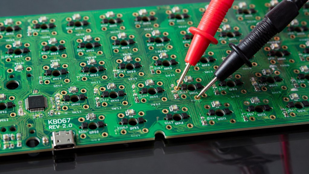
Using a multimeter to check continuity and power lines is a fundamental step in troubleshooting your mechanical keyboard’s PCB. It helps verify if switches, diodes, and traces are properly connected. Set your digital multimeter to continuity mode and test between switch pins, rows, and columns, listening for beeps that confirm good connections. Check the USB connector pins for data and power—ensure the 5V line reads between 4.8V and 5.2V. Additionally, measure voltage on main power rails like 5V and 3.3V to confirm stability. Use the multimeter to detect shorts by probing between ground and power lines. Carefully inspect solder joints for cracks or cold joints, especially around critical connections. When working with hot-swap PCBs, paying attention to the electrical ratings ensures safe handling during testing.
Step-by-Step Testing of Switch Contacts and Diodes
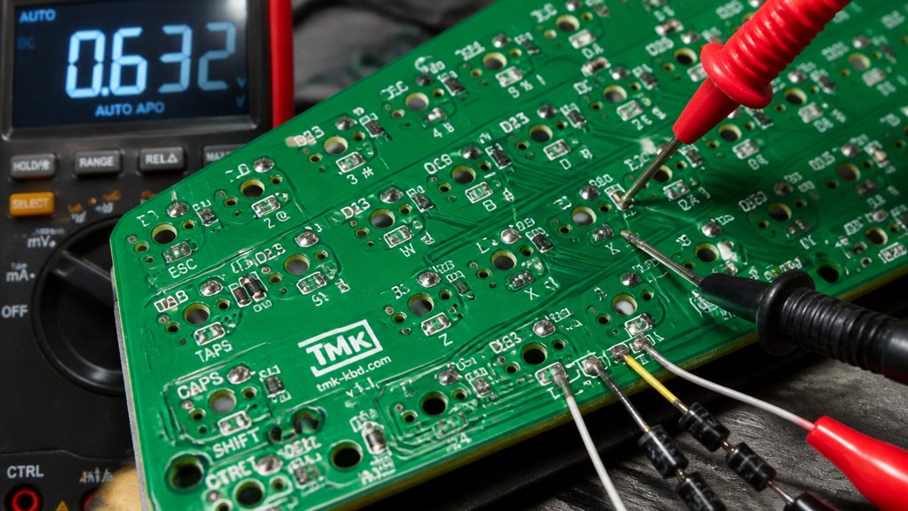
To accurately test switch contacts and diodes on your PCB, start by visually inspecting the diode orientation. Verify the cathode (black band) aligns with the PCB markings; reversed diodes can disrupt matrix connectivity and cause unregistered keys.
Next, use a metal tweezers to short the two switch pin pads, testing each switch socket from either side. Confirm circuit continuity with a multimeter in mode, checking that traces and diode connections are intact and free of shorts.
Pay attention to hot-swap sockets, making sure pins are fully seated and solder joints are solid.
For layer or combination keys, hold the key down and short the pins to verify correct key registration.
Additionally, ensure that diodes are functioning correctly by testing their power rating, as improper ratings can affect their performance and protection capabilities.
This process guarantees your PCB’s switch contacts and diodes are functioning correctly before further testing.
Troubleshooting Firmware and Software Issues During PCB Checks
When troubleshooting firmware and software issues during PCB checks, start by reflashing the firmware using tools like QMK Toolbox and guarantee you’re in bootloader mode with buttons such as ATm32U4DFU.
Confirm that your software, like VIA, is compatible and updated to recognize all key functions, including special keys.
Remember to differentiate between hardware faults and software glitches by retesting after firmware resets and verifying correct configurations.
Additionally, ensure that your microcontroller support and wiring setup align with the firmware requirements, preventing common compatibility errors.
Firmware Reflashing Procedures
If your mechanical keyboard’s PCB isn’t responding or behaves erratically, reflashing the firmware can often resolve these issues. To do this, you need to access the bootloader mode on the PCB, typically using a reset or DFU button (e.g., labeled ATm32U4DFU).
Once in bootloader mode, make sure the PCB is connected via USB and recognized by your computer. Use tools like QMK Toolbox to load the correct firmware binary that matches your keyboard’s layout and microcontroller. Additionally, ensure the firmware supports your switch compatibility and layout specifications to prevent further issues.
Carefully follow these steps:
- Press and hold the reset or DFU button to enter bootloader mode
- Connect the keyboard to your computer via USB
- Confirm recognition by your PC
- Load the correct firmware binary with flashing tools
- Wait for the process to complete before unplugging
This process restores the mechanical keyboard’s firmware, fixing unresponsiveness caused by corruption.
Software Compatibility Checks
Guaranteeing your keyboard’s software is compatible with the firmware on the PCB is essential for reliable operation. Start by confirming the device is properly recognized by your computer system. Successful recognition and correct device enumeration are vital steps before testing key functionality.
Use keyboardtester.com to verify standard key presses, but remember it can’t detect special layer or lighting functions—these rely entirely on internal firmware handling. To test special keys, such as function layers or lighting controls, use VIA software, which can visually illuminate keys in the interface, helping you identify firmware-handled functions. Additionally, ensuring you have the correct support for your specific firmware type, such as QMK or VIA, can prevent firmware glitches and improve overall testing accuracy.
Firmware glitches can mimic hardware issues; restoring default keymaps through VIA or reflashing the firmware often resolves false negatives during PCB connection tests. Proper software compatibility guarantees accurate detection and communication with your PCB.
Advanced Diagnostics for Complex PCB Faults
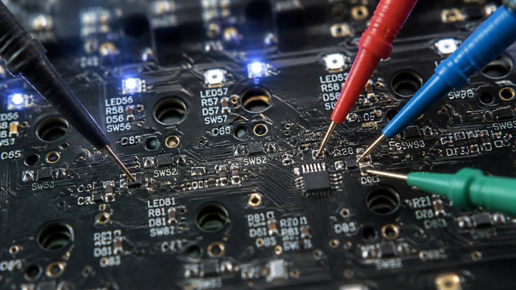
Advanced diagnostics are essential when troubleshooting complex mechanical keyboard PCBs that exhibit elusive faults. You need to analyze the printed circuit board thoroughly using specialized tools.
Techniques include:
- Using oscilloscopes, LCR meters, and IV tracers to examine signal integrity and pinpoint faulty components or trace issues.
- Implementing in-circuit testing (ICT) and JTAG debugging for precise fault localization and firmware updates.
- Employing X-ray inspection and Automated Optical Inspection (AOI) to uncover hidden defects like cracks, cold solder joints, or micro-solder bridges.
- Carefully inspecting JST cables and daughterboards for proper pin alignment and connectivity to prevent communication failures.
- Comparing voltage levels and testing continuity at critical points with multimeters to detect shorts, voltage drops, or reversed polarity affecting operation.
Replacing or Repairing Damaged PCB Components
When repairing damaged PCB components on a mechanical keyboard, start by carefully inspecting the affected areas for traces, pads, or components that show obvious damage or lifting.
For minor trace damage, use conductive paint or jumper wires soldered to scraped copper areas to restore continuity.
If you encounter lifted pads, wiring thin wires to the nearest vias or component leads is a temporary fix, but consider a replacement PCB for more severe damage or discontinued boards.
When replacing faulty diodes, make certain you use correctly oriented 1N4148 types, matching cathode markings on the PCB to maintain proper key matrix function.
Reflow cold or weak solder joints, especially on hotswap sockets or component leads, with a temperature-controlled soldering iron, using 99% isopropyl alcohol for cleaning.
Frequently Asked Questions
How to Test if a Keyboard PCB Works?
You connect the PCB to your computer via USB, then use software like VIA or keyboardtester.com to verify key presses. Short switch pin pads with tweezers to test response, and perform continuity checks on traces with a multimeter.
How to Check Connection in PCB?
You check connections on the PCB by using a digital multimeter in continuity mode across traces, switch pins, and diodes, inspecting visually for damage, and verifying power and USB connections to confirm proper circuit continuity and functionality.
Can You Test a PCB With a Multimeter?
Yes, you can test a PCB with a multimeter. Use it to check continuity, voltage levels, and resistance in traces, switches, and connections to identify faults like broken circuits, shorts, or cold solder joints.
How to Know if PCB Is Faulty?
You’ll know your PCB is faulty if switches don’t register, visual signs like burns or damaged traces appear, continuity tests show broken lines, or you can’t enter firmware mode or get consistent computer recognition during testing.
In Summary
Testing your mechanical keyboard’s PCB guarantees it functions perfectly and catches issues early. By following visual inspections, using a multimeter, and methodically testing switch contacts, diodes, and power lines, you can identify problems accurately. Don’t forget to troubleshoot firmware or software glitches as needed. If you find damaged components, replace or repair them promptly. Regular testing keeps your keyboard in top shape, providing a seamless typing experience and extending its lifespan.