The best way to test your keyboard matrix is by combining manual continuity checks with automated firmware scans. Use a multimeter to verify each wire and connection for shorts or breaks, and employ microcontroller tools like CircuitPython to scan and verify key presses in real time. Focus on proper wiring, grounding unused pins, and checking for ghosting or conflicts. Continuing further will reveal essential tips to guarantee your keyboard works perfectly from hardware to firmware.
How to Test Your Keyboard Matrix for Connectivity and Wiring Issues
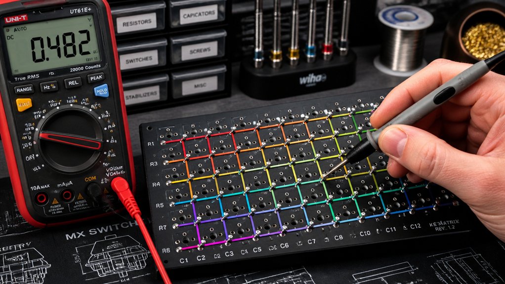
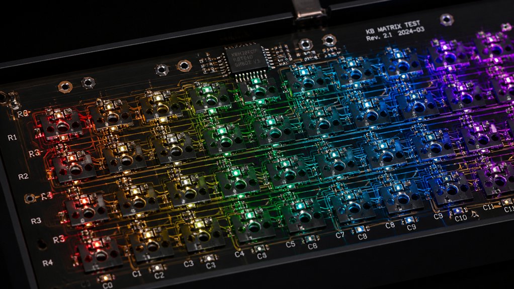
Before diving into more complex troubleshooting, it’s essential to verify that your keyboard matrix’s wiring and connections are solid. Start by using a multimeter in continuity mode to check the electrical connections between each row and column pin. Guarantee there are no breaks or shorts, which can cause unreliable key presses.
You can also employ an automated matrix scanning script on a microcontroller like the Raspberry Pi Pico with CircuitPython. This script helps sequentially drive pins LOW and read others, revealing connected pins and possible wiring errors.
Make sure all unused or unmapped pins are grounded to prevent floating inputs that lead to false detections.
Finally, physically inspect solder joints, ribbon cables, and breakout contacts to confirm secure, damage-free connections, avoiding interference during testing. Additionally, consulting the safety ratings of your multimeter can ensure you’re working within safe parameters while testing your keyboard matrix.
Identify Ghosting and Key Conflicts in Your Keyboard
To spot ghosting and key conflicts, you need to systematically test combinations of keys that share rows or columns, paying attention to any unexpected simultaneous presses. Using tools like a multimeter or a Raspberry Pi Pico can help reveal wiring issues or always-connected pin pairs that cause ghosting. Monitoring your keyboard during live testing can also uncover false keypresses, especially on no-diode matrices, indicating wiring or conflict problems. Additionally, understanding the GPIO configuration of your controller can help diagnose and mitigate potential wiring conflicts that lead to ghosting.
Detecting Ghosting Effects
Have you ever experienced keys registering when you haven’t pressed them, or noticed unintended keystrokes during fast typing? That’s often a sign of ghosting, caused by multiple key presses creating unintended signals.
To detect ghosting effects, you can use matrix scanning: press three keys that form a rectangle across two rows and columns, then observe if a fourth unpressed key registers. This indicates ghosting due to current flow through unintended paths.
You can also perform a continuity test with a multimeter between row and column lines while pressing keys—unwanted connections reveal ghosting issues.
Keyboards with diodes prevent ghosting by directing current flow, whereas no-diode designs might require firmware ghost filtering or manual testing.
Implementing proper circuit layout and including diodes in your keyboard matrix design can significantly reduce ghosting problems, ensuring more accurate key detection.
Systematic matrix scanning helps identify these ghosting effects reliably.
Mapping Key Conflicts
Mapping key conflicts requires systematically testing your keyboard’s matrix to identify ghosting and wiring issues. You should press multiple keys simultaneously, paying attention to whether unpressed keys register falsely—a sign of ghosting caused by shared wiring without diodes.
Use matrix scanning techniques that drive rows low one at a time and read columns, revealing conflicts when unexpected signals occur. Experimentally verify diode presence and orientation by scanning in both drive directions; this helps distinguish between ghosting and legitimate key presses. Material, Base Stability, and Weight Considerations—using sturdy, heat-resistant materials can ensure consistent testing without accidental damage to the board.
Automated tools like Raspberry Pi Pico and CircuitPython can streamline this process by quickly detecting always-connected pins or overlapping key responses. Notice erratic or extra key events during tests—all indicate key conflicts that may require adding diodes or modifying the scanning logic to improve accuracy.
Troubleshooting Wiring Issues
When troubleshooting wiring issues in your keyboard matrix, start by using a multimeter to check continuity between rows and columns while pressing individual keys. This helps identify unintended connections that cause ghosting or key conflicts.
Focus on key presses one at a time, watching for unexpected outputs, which often indicate wiring errors or missing diodes.
- Use a matrix scanner to perform a static baseline scan, revealing always-connected pin pairs that signal wiring faults.
- Narrow probe points to only wired pins to isolate problematic lines responsible for ghosting.
- Verify all unused multiplexor or CMOS chip input pins are grounded to prevent false key activations.
- Consider using hot-swap PCBs to test different switches easily during troubleshooting, reducing the risk of soldering errors affecting the matrix.
These checks help pinpoint wiring issues, ensuring accurate detection of ghosting and conflicts caused by faulty wiring or connections.
Manual Methods: Using Continuity Testing and CircuitPython Scanning
Manual methods for testing keyboard matrices rely on basic tools like a multimeter to verify electrical connections between rows and columns directly. Manual continuity testing involves probing each pair of switch contacts to confirm connections, but this process can be time-consuming and error-prone due to small pin spacing and numerous wiring combinations.
Alternatively, CircuitPython scanning automates this task by sequentially driving GPIO pins LOW and reading others on a Raspberry Pi Pico. This method quickly maps key connections, identifies baseline pin pairs, and classifies pins as matrix candidates, GND, VCC, or floating.
It also detects diode directions when you press keys interactively. Saving the full serial output from CircuitPython scanning enables an accurate, efficient reconstruction of the keyboard matrix, greatly speeding up development and reducing mistakes compared to manual continuity testing. Additionally, employing matrix testing techniques can help ensure comprehensive evaluation of key connections and prevent potential circuit faults.
Troubleshoot Bouncing and Debouncing Challenges
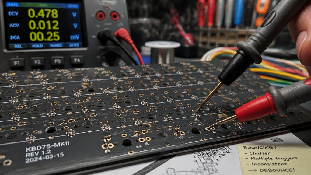
Once you’ve successfully mapped your keyboard matrix or automated the scanning process, the next step is ensuring reliable key detection. Bouncing can cause false triggers, so you need effective debouncing strategies for your rows and columns. To troubleshoot challenges, consider these approaches: – Use analog RC low-pass filters on column lines to filter out EMI noise and stabilize signals. – Implement digital debouncing algorithms that count consecutive identical samples, reducing false triggers. – Combine counters with state machines for hybrid debouncing, balancing fast response with noise immunity. Additionally, selecting appropriate switch types (linear, tactile, clicky) and understanding their actuation force can influence how bouncing impacts signal stability. These methods help address bouncing, ensuring clean signals during scanning. Proper debouncing improves reliability and reduces false key presses, making your keyboard matrix function smoothly.
How to Automate Firmware-Based Key Testing With Raspberry Pi Pico
Automating firmware-based key testing with a Raspberry Pi Pico streamlines the process of verifying your keyboard matrix, eliminating the tediousness of manual continuity checks. A thorough understanding of QMK firmware support for your keyboard layout ensures that the testing procedure accurately reflects the firmware’s behavior. You connect your keyboard’s row and column pins through an FPC breakout board with male headers to the Pico’s output pins, wiring them sequentially for easy auto-detection. Using CircuitPython in Thonny IDE, you run multi-phase scripts that first establish static baseline scans to identify connected lines, then guide you through interactive key mapping and diode polarity testing. Live scan mode provides real-time feedback through the serial terminal, showing which keys are pressed or released. Save this scan data as `info.json` to assist in firmware development, ensuring accurate key detection and smooth integration into USB HID keyboard firmware.
Detect and Fix Switch Bouncing for Reliable Key Detection
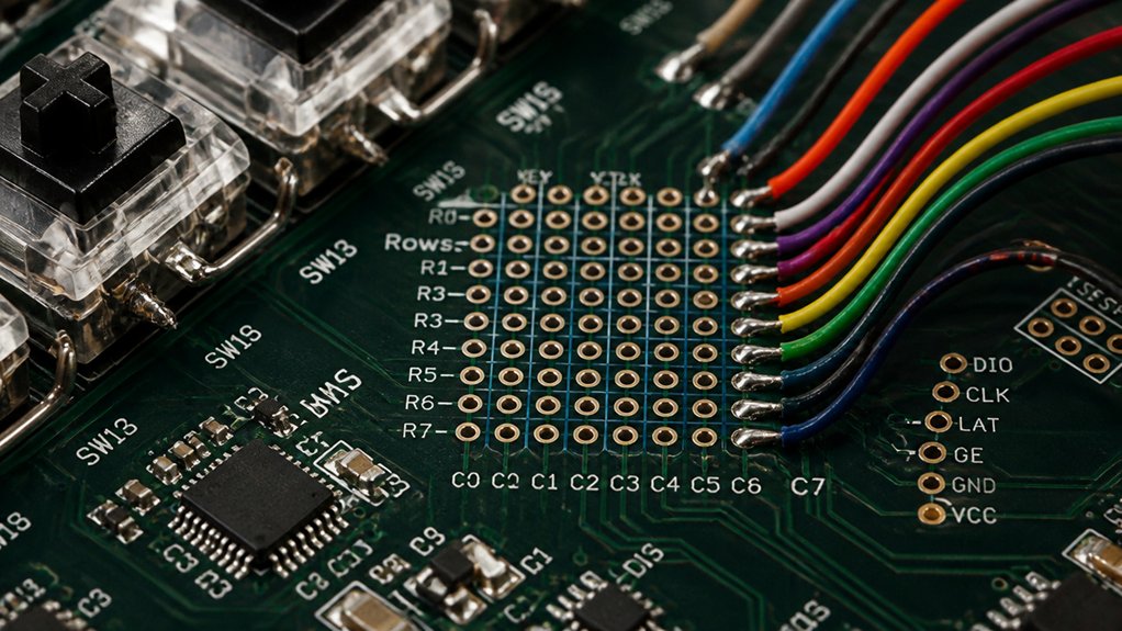
To guarantee reliable key detection, you need to address switch bouncing effectively. You can use both hardware solutions like RC filters and software algorithms such as integrator or hybrid debouncing techniques. Choosing the right approach depends on your specific needs for speed and noise immunity. Additionally, selecting appropriate lubricants can help reduce mechanical noise and improve the overall stability of switch signals.
Debouncing Techniques Overview
Debouncing techniques are essential for ensuring reliable key detection in keyboard matrices since mechanical switches tend to generate multiple signals during a single press or release due to contact bounce.
To improve debouncing, you can implement methods like counting consecutive stable samples, which confirms a key state change with high confidence but adds latency.
Integrator or accumulator methods use a saturating counter, switching output only after thresholds, reducing delay while maintaining robustness.
Hybrid algorithms combine counters with state machines to detect transient states, allowing immediate output changes for both key press and release.
Additionally, implementing switch film influences can help stabilize switch behavior and minimize contact bounce, improving overall debounce effectiveness.
- Count consecutive stable samples for reliable debouncing
- Use counter-based integrator methods to reduce delays
- Apply hybrid algorithms for low latency and high robustness
Hardware and Software Solutions
Ensuring reliable key detection in keyboard matrices requires effective hardware and software solutions to detect and eliminate switch bounce. Hardware methods, such as using a Raspberry Pi Pico with FPC breakout boards and ribbon cables, automate pin scanning, replacing manual probing and ensuring a precise pin map. This setup rapidly identifies switch connections and isolates faulty contacts.
Software techniques, like debouncing algorithms—integrator counters and hybrid state machines—filter out mechanical bounce (~5 ms) and EMI noise during matrix scans. Low-pass RC filters on column lines further reduce artifacts without slowing scan speed.
To enhance reliability, counting consecutive stable samples confirms key states, while advanced methods like LSTM neural networks adapt to complex bounce patterns. Together, these hardware and software strategies improve key detection accuracy and responsiveness.
Monitor Real-Time Key Presses With Serial Output
Using CircuitPython on a Raspberry Pi Pico allows you to scan your keyboard matrix’s pins and output key press events directly to the serial terminal in real-time. You can monitor which keys, such as “one” or “row,” are pressed or released instantly, helping verify wiring and firmware.
After wiring the matrix to Pico GPIOs, run live scanning, and the serial output will log each key event with labels for clarity. This output continuously updates until you stop it, providing immediate feedback.
To deepen testing, pay attention to:
- Correct mapping of each key and label
- Real-time detection of simultaneous key presses
- Clear differentiation between press (↓) and release (↑) events
This method offers an efficient way to troubleshoot and verify your keyboard matrix during development.
Best Practices for Wires, Pin Assignments, and Layout
To guarantee reliable testing, you should use ribbon cables with a consistent pitch and male header pins for clear connections between your keyboard matrix and microcontroller. Assign pins sequentially to rows and columns to make wiring straightforward and take advantage of auto-detection in your scanning scripts.
Additionally, organize and label your pin layout carefully, and ground unused inputs to prevent false readings.
Optimized Wiring Techniques
Optimized wiring techniques are essential for reliable keyboard matrix testing, as they secure signals are clear and easily identifiable during automated scans. To achieve this, assign column pins and row lines sequentially and logically, making it easier to identify roles during troubleshooting.
Use soldered male header pins directly connected to dedicated microcontroller pins, such as GPIO 2-22 and 26-28 on a Raspberry Pi Pico, for consistent connections. Avoid placing breakout boards on shared power rails to prevent shorts and signal interference.
Guarantee wiring layouts are clean and clearly labeled, simplifying troubleshooting during baseline and interactive tests. Additionally, ground all unused input pins on multiplexers or matrix lines to eliminate floating signals, noise, and false detections, assuring stable and accurate testing conditions.
Strategic Pin Layout
A well-planned pin layout is essential for reliable keyboard matrix testing, as it simplifies scanning and troubleshooting. Assign matrix row and column pins sequentially to GPIOs, such as GPIO 2-22, 26-28 on a Pico, so automated scripts can easily detect their roles without manual mapping.
Guarantee wires are organized to match the pin numbers with their corresponding rows and columns, reducing confusion. Use ribbon cables with FPC breakouts and male header pins for secure, consistent connections, avoiding breadboard rails to prevent shorts.
Keep ground and VCC lines separate and verify their connectivity in initial scans to prevent false readings. Limit probe pins to wired matrix lines and avoid floating or unused pins, which can introduce noise or phantom detections.
Proper wiring minimizes crossovers and maintains clear row-column associations for accurate testing.
Compare Different Testing Methods: Pros, Cons, and Use Cases
When comparing different keyboard testing methods, it’s important to weigh their advantages, limitations, and ideal scenarios.
Manual continuity meter testing offers direct verification of input and output connections, but it’s slow and prone to human error, especially with large matrices.
Manual testing verifies connections directly but is slow and error-prone for larger keyboards.
Automated scanning with microcontrollers like the Raspberry Pi Pico speeds up the process, reduces wiring mistakes, and quickly detects pin LOW states across rows and columns.
Software-based methods allow you to map key functions precisely and confirm diode direction, boosting firmware accuracy.
Live scan testing provides real-time feedback, helping you troubleshoot while testing.
Advanced techniques, such as serial output logs and JSON data export, are ideal for large or custom keyboards, streamlining integration with firmware platforms like QMK.
Final Tips for Validating and Finalizing Your Custom Keyboard
Before finalizing your custom keyboard, it’s essential to thoroughly validate its wiring, functionality, and firmware to prevent issues later on.
Save the complete serial output from all scanning phases to verify accurate key mappings for firmware development. Perform live scan testing to confirm that pressing a key produces the expected detection, ensuring real-time feedback matches physical keys, which might work smoothly but still needs checking.
Use a multimeter to check wiring continuity, especially for GND connections, and resolve “too few matrix candidates” errors. Also, double-check that the host OS’s keyboard layout matches your physical arrangement to avoid typing errors.
After testing, deploy your final firmware code.py on your CircuitPython device and confirm the Pico registers as a USB keyboard with no unmapped keys, ensuring your keyboard is ready for use.
Frequently Asked Questions
How Can I Identify Stuck Keys in My Keyboard Matrix More Efficiently?
You can identify stuck keys efficiently by using a key testing software or firmware, pressing each key individually while monitoring output signals. This rapid feedback helps pinpoint stuck keys without manually testing every key.
What Tools Are Best for Diagnosing Intermittent Key Faults?
You should use a multimeter to check for continuity and a keyboard tester software to identify intermittent faults. These tools help you swiftly diagnose issues, revealing wiring problems or faulty switches causing the intermittent key behavior.
How Does Scanning Speed Affect Keyboard Matrix Testing Accuracy?
Faster scanning speeds can improve detection of quick, intermittent faults by quickly identifying irregularities, but excessively high speeds might cause missed signals or false positives. Adjust your speed to balance accuracy and detection reliability during testing.
Can Software-Based Testing Detect All Wiring Issues?
Software-based testing can detect many wiring issues, such as broken traces or stuck keys, but it may miss physical problems like broken connectors or damaged wiring. Combining software tests with physical inspections guarantees the most thorough diagnosis.
What Are Common Mistakes to Avoid During Keyboard Matrix Testing?
You should avoid skipping continuity checks, neglecting to verify connections at each point, rushing the testing process, and ignoring potential short circuits. Carefully follow testing procedures, double-check connections, and systematically verify each key and wiring to prevent mistakes.
In Summary
To sum up, testing your keyboard matrix thoroughly guarantees reliable performance and longevity. Use a combination of manual checks, continuity tests, and automated firmware scans to identify issues early. Keep your wiring neat and well-organized, and always validate your setup before final assembly. By following these methods and best practices, you’ll create a dependable, fully functional custom keyboard that’s ready for daily use. Stay meticulous, and your efforts will pay off in the end.